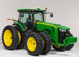
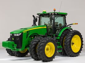
8370R Tractor
- John Deere
- Row Crop Tractors 8 Series Row-Crop Tractors
Find Your Nearest Location
Key Features & Specs
- 370 Engine hp
- John Deere PowerTech™ 9.0L PSS
- Choice of 16-speed PowerShift, e23™ PowerShift, or Infinitely Variable Transmission (IVT™)
- MFWD, or Independent Link Suspension (ILS™)
- Engine HP 370
- Wheel/Track Wheel
- Hydraulics Closed-center, pressure and flow compensated with 4 standard SCV (5 and 6 available)
- Cabs CommandView™ III
- Transmission Options e23™ PowerShift with Efficiency Manager; standard AutoPowr™ IVT™
- Suspension Independent Link Suspension (ILS™)
- + Expand All
- - Close All
-
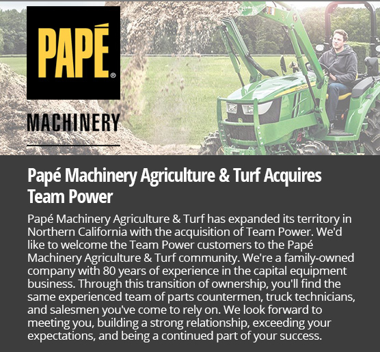
Lighting packages provide 360 degrees of coverage for maximum productivity
 Premium lights

The 7R, 8R, and 8RT Series Tractors feature two lighting package options:
- Standard
- Premium
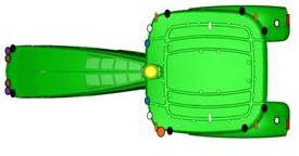
The cab lighting pattern provides 330 degrees of coverage while the hood lighting provides the remaining 30 degrees for completely programmable 360-degree, stadium-style lighting. This ensures there are no dead zones or lighting adjustments needed. The lighting configurations are available to match various applications and ensure maximum around-the-clock productivity.
Bulb housings are large, allowing for optimum total lumens and available light. The standard lighting packages use 65-W halogen bulbs, whereas the premium lighting package uses light-emitting diode (LED) lights. In the premium lighting package, these tractors take advantage of the high-performing and efficient LED technology.The low- and high-beam driving/work lights are adjustable. Please refer to the electrical section in the operator’s manual for complete details on adjusting lights.
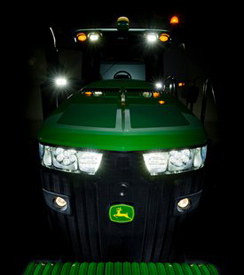
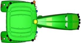
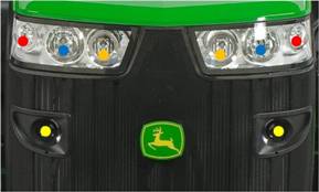 7R/8R/8RT lighting
Yellow circles
- All lighting packages: 65-W halogen: road low beam
Red circles
- Standard: 65-W halogen
- Premium: LED
Blue circles
- Standard: 65-W halogen; field and road high beams
- Premium: LED
Orange circles
- Standard: blank
- Premium: LED

Adjustable high-beam driving light/work light

License plate bracket with light

Rotary beacon

Fixed halogen light

Adjustable low- beam driving light/work light

Fixed amber light

Adjustable halogen light

Adjustable mid-body halogen light

Fixed high-intensity discharge (HID) light

Adjustable HID light

Mid-body hazard, turn, and width indicating light

Amber turn and brake light
Standard lighting
 Standard lighting (8R)
 Standard lighting (7R)
Six front grill-mounted lights:
- Two 65-W low-beam driving/work lights (mid grill screen)
- Two 65-W high-beam driving/work lights (top of grill screen, hood mounted)
- Two front corner-facing halogen work lights (top of grill screen, hood mounted)
10 cab roof-mounted lights:
- Two rear-facing 65-W floodlights
- Four side-facing 65-W floodlights
- Four corner-facing amber lights
Other lights:
- Two rear fender-mounted floodlights
- Two rear turn signal and brake/tail lights (fender mounted)
- Two folding-extremity lights
Plus these lights:
- Two adjustable front roof 65-W halogen floodlights
- Two front belt-line floodlights
- Rotary beacon light
Premium lighting
Eight front grill-mounted lights:
- Two 65-W low-beam halogen driving/work lights (mid grill screen)
- Two LED high-beam driving/work lights (top of grill screen, hood mounted)
- Two front corner-facing LED work lights (top of grill screen, hood mounted)
- Two front-facing LED working lights (top of grill screen, hood mounted, inner position on the sides)
12 cab roof-mounted lights:
- Four side-facing LED lights
- Four corner-facing amber lights
- Two rear-facing LED lights
- Two adjustable front roof LED lights
Other lights:
- Two rear fender-mounted LED lights
- Two rear turn signal and brake lights (fender mounted)
- Two folding-extremity lights
- Two front belt-line LED floodlights
- Rotary beacon light
The premium lighting package replaces all previous halogen and HID lights with LED lights. The only lights that are not LED are the low-beam driving lights, they remain halogen. This allows each LED light to work at a lower temperature and no one light works harder than any other. The uniformity in LED coverage allows only one type of light output surrounding the tractor.
The lighting pattern in the premium package provides industry-leading performance in nighttime visibility. LED bulbs provide maximum brightness and a true color output for excellent field definition that is easy on the operator's eyes.
The LED lights provide 40 percent greater coverage width and 10 percent more light coverage in the rear. LED lighting packages use 45 percent less amps than standard halogen lights and have an increased life expectancy over HID lights which leads to lower costs of ownership over the life of the tractor.
NOTE: Lighting packages may vary depending on region.
Selecting a lighting mode/programmable lighting
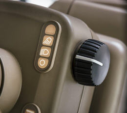 Lighting mode selector
Operators can quickly select a lighting mode on the steering console:
- Lights, off position
- Road lights
- Field lights
 The CommandCenter™ display
The CommandCenter display allows operators to customize light settings. Operators can select only the lights they need or want for a given application and store these settings. The operator-programmed configurations can then be turned on or off with the push of a button on the CommandARM™ controls.
- Programmable field lights 1
- Programmable field lights 2
- Beacon light
- Emergency flashers
NOTE: Road/loader lights are also referred to as high-mounted driving lights for use in front hitch applications that obscure the headlights. See the Attachments section.
The battery power saver feature is also standard. When the engine is off and the outside lights have been left on, this feature is designed to avoid battery run down.
After the lights have been left on for 30 minutes and the key is in the off position, the lights cycle or blink on and off five times as an alert. The lights continue to illuminate for one more minute and then automatically shut off to protect the battery.Field-installed options
Field-installed options are also available. To find this information, use the Build Your own Configurator application for US/Canada or Build & Price in John Deere Sales Centre for Australia/NZ.
Programmable exit lighting
Another feature is programmable exit lighting. Exit lighting allows the lights outside the cab to stay on for up to 300 seconds. They can be programmed in increments from 0 to 300 seconds.
Refer to the operator’s manual for complete instructions on programming field, driving, and exit lighting.
Option code Description 7201 Standard lighting 7206 Premium lighting -
ActiveCommand steering (ACS™) provides a robust and full-encompassing steering system
ACS overview
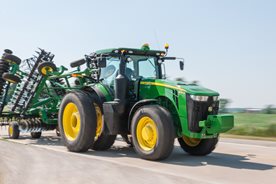 8R in transport

With ACS, John Deere has designed one of the most robust and full-encompassing steering system in the industry. Whether in the field or on the road, ACS reduces steering effort, which can result in reduced operator fatigue and can improve operator comfort.
There are four key features of the ACS system:
Dynamic road wheel offset:
- A gyroscope senses tractor yaw and can automatically make small steering adjustments to provide unprecedented line-holding abilities. Drive down a bumpy road and experience how ACS makes it easier to keep the tractor straight, even over rough terrain. ACS delivers the ultimate in comfort.
- ACS works to prevent over-steering when a sudden obstacle causes the operator to make a quick steering reaction.
Variable ratio steering:
- Approximately 3.5 turns lock-to-lock at in-field speeds for quick headland turns.
- Approximately 5 turns lock-to-lock at transport speeds.
Elimination of steering slop and hand wheel drift:
- Steering wheel drift and slop are eliminated with the ACS electronic control system.
Variable effort steering:
- Steering wheel resistance automatically changes with ground speed to deliver light steering effort at slower speeds for less effort during headland turns, and higher steering wheel torque at transport speeds for better comfort.
A fail operational system
The ACS system is fail operational, which means steering is still functional in the event of any single-point failure. John Deere has gone to great lengths to help ensure the operator has the ability to steer the tractor if something goes wrong in the steering system.
For example, if the primary controller fails, a second controller takes over. If power from the alternator fails, the battery resumes control. If the engine quits running and is unable to supply hydraulic oil to the system, an electric-driven backup pump is used to supply the oil. There is a backup for ACS components.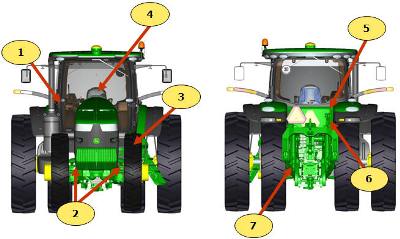 ACS components
The ACS system consists of several key components:
- Gyroscope: this is used to measure the yaw rate (turn rate) of the tractor during transport speeds.
- Road-wheel angle sensors: these sensors simply measure the steer angle of the tractor.
- Power supply module: this module distributes the power of the battery and alternator throughout the ACS system.
- Hand-wheel angle sensors and tactile feedback unit: this includes the steering wheel position sensors and a brake which can increase or decrease resistance dependent on speed. Lighter feedback is desired during normal field use, and slightly heavier feedback is desired during transport and while the tractor is cornering at high speeds.
- Controllers: two controllers are located in the back of the tractor and are the brains of the system.
- Control valves: also known as steering valves, control valves are used to steer the tractor.
- Electric-drive backup pump: this pump supplies oil to the steering system, brakes, and park (for towing) brake if there is no longer a sufficient oil supply to the steering and brakes.
Value of ACS
- Improves line holding when driving at transport speeds
- Fewer turns lock-to-lock: 3.5 turns lock-to-lock in the field for quicker headland turns and 5 turns lock-to-lock at transport speeds
- Eliminates hand wheel backlash and drift
- Reduces steering effort results in reduced operator fatigue
- Smaller hand-wheel diameter for improved operator comfort and visibility
- Maintains operator feel and touch-points of traditional steering column system
- Fully integrates with AutoTrac™ guidance assisted steering stems
- Compatible with suspended and non-suspended front axles
- Compatible with wide and narrow section width tires
-
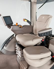
Standard CommandView™ III cab offers unsurpassed amenities
 CommandView III cab
The Standard CommandView III cab offers unsurpassed visibility, operator comfort, control placement, and ride and sound quality.
Features:- ComfortCommand™ seat with air suspension, lumbar support, swivel, fore-aft and lateral attenuation, backrest angle adjustment, adjustable left-hand armrest, and 40-degree right-hand seat swivel
- Operator presence system that warns if the operator is out of the seat while operating key functions
- Folding instructional seat
- CommandARM™ console with integrated controls
- 4100 or 4600 Generation 4 CommandCenter™ display
- Behind-the-seat storage
- Left-hand storage compartment
- Passive noise reduction system
- Service ADVISOR™ data port
- Tilt/telescoping steering wheel with position memory
- Swing-out rear window that opens 30 degrees
- Right- and left-outside mirrors (manually adjustable mirror head)
- Monitor mounts on right-hand front post and rear cab post
- Standard radio package, including AM/FM stereo and weatherband with remote controls, auxiliary input jack, four speakers, and an external antenna
- Laminated glass
- Air conditioner and heater with automatic temperature controls (ATC)
- Two 12-V convenience outlet (cigarette lighter style)
- One 12-V three-pin outlet with adapter (provides switched and unswitched power)
- One International Organization for Standardization (ISO) nine-pin connector
- Power strip with convenience plug adapter
- Hitch control lever lock and selective control lever lock
- Two-speed and intermittent front and rear wiper with washer
- Front pull-down sunshade
- Digital cornerpost display with:
- Fuel level gauge, including low fuel warning
- Temperature gauge
- Diesel exhaust fluid (DEF) gauge, including low DEF warning
- Engine rpm
- Transmission commanded gear or speed
- Vehicle system functions, such as iTEC™ system, that are operating
- Inside-mounted rearview mirror
- Beverage holders sized to accommodate various containers
- Interior left-hand dome light
ComfortCommand seat
 ComfortCommand seat
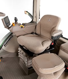
ComfortCommand seat improves ride quality and helps to reduce operator fatigue.
Features include:- Armrests, lumbar support, and backrest angle are easily adjusted to match operator preference.
- Shock absorbers dampen the motion effect of the tractor for an improved ride.
- Seat height adjustments are conveniently located on the left armrest.
- Fore-aft adjustment is easy to reach located on the left front of the seat.
- Swivel adjustment, located on the front of the seat, allows the seat to be swiveled 40 degrees to the right or eight degrees to the left of the center position.
- Operator presence switch warns if the operator is out of the seat while operating key functions.
- Seat belt retractor.
- Centered cab seat provides excellent over-shoulder visibility.
- Adjustable shock absorber permits ride adjustment from soft to firm to match the operator's desired comfort level.
- Removable cushions allow for easy cleaning.
 Fingertip paddle pots
 Encoder wheel
CommandARM
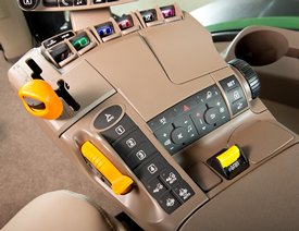 CommandARM controls
John Deere 7R and 8R Series Tractors feature the CommandARM with integrated Generation 4 CommandCenter display. The control layout of the CommandARM utilizes a clean and efficient design which groups controls by function and builds upon John Deere’s history of intuitive and ergonomic control placement and operation. The design of the CommandARM allows for a 40 degree right seat swivel and adjustable positioning matching the operator’s preference.
Controls located on the CommandARM include:
- Engine throttle
- FieldCruise™ system
- Minimum engine speed – CommandQuad™ transmission, 16-speed PowerShift™ transmission (PST), e23™ transmission
- Eco mode – Infinitely Variable Transmission (IVT™)
- Foot pedal lock (if equipped)
- Transmission control
- Hitch/selective control valve (SCV) controls
- Rotary encoder hitch control
- Power take-off (PTO) controls
- Mechanical front-wheel drive (MFWD) on/automatic
- Differential lock on/automatic
- iTEC sequence switches
- AutoTrac™ assisted steering system resume switch (if equipped)
- Joystick (if equipped)
- Radio
- Beacon light on/off
- Hazard lights on/off
- Field lights 1/2
- Heating, ventilation, air conditioning (HVAC) system
Transmission controls
John Deere 7R Series Tractors with CommandQuad transmissions feature a left-hand reverser. 8R Series Tractors equipped with 16-speed PST are equipped with right-hand reverser. 7R Series Tractors equipped with e23 PST offer a left- or right-hand reverser. 7R or 8R Series Tractors equipped with AutoPowr™/IVT transmissions are offered with either a left-hand or a right-hand reverser.
The transmission control lever is placed on the left side of the CommandARM closest to the operator for convenient setting and adjustment.
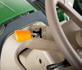 Left-hand CommandQuad/e23 reverser
 Right-hand IVT and PST reverser
 16-speed PST right-hand reverser
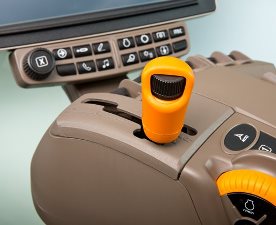
Hydraulic and hitch controls
Hydraulic and hitch controls utilize fingertip paddle pots for raise/lower and extend/retract functions. An optional crossgate joystick replaces fingertip paddle pots for control of SCVs and allows for programmable hydraulic functionality according to operator preference. Rear hitch position can also be controlled with the encoder wheel located on the right side of the CommandARM. The encoder wheel allows for finite positioning of the rear 3-point hitch.
Three buttons near the encoder are for hitch set, lock, and return to height. Adjustment knobs for the 3-point hitch are located under the cover for the CommandARM control's storage compartment and allow for adjustment of the rate of drop, hitch height limit, and depth control.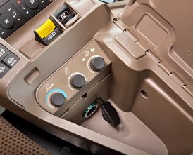 Hitch controls
 Optional crossgate joystick
Throttle
The throttle design incorporates buttons which control FieldCruise speed, foot pedal mode (if equipped), and transmission eco settings.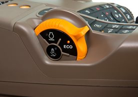 Throttle
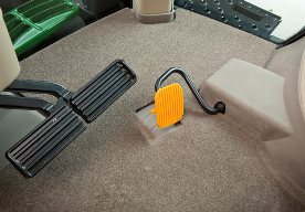 Foot throttle
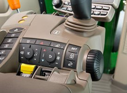
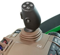
Tractor function controls
Located just to the right of the throttle is the AutoTrac activation button and four sequence controls for iTEC functions. Behind the iTEC sequence controls, there are buttons which control the activation and deactivation of MFWD and differential lock.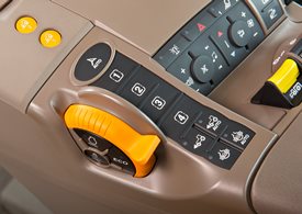 AutoTrac resume and iTEC strip
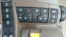
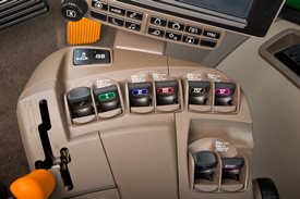
Controls for radio, lights, rotary beacon (if equipped), hazard flashers, and HVAC system are located to the center-right on the CommandARM, along with PTO for both front (if equipped) and rear PTO.
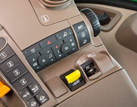 Radio, HVAC, hazard flashers, and PTO controls
Seat swivel
The design of the CommandARM allows for up to 40 degrees of right-hand seat swivel.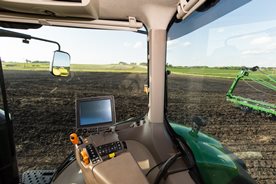 Seat swivel
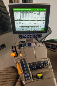
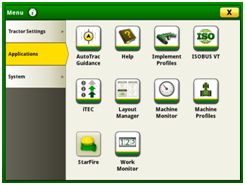
CommandCenter
 Generation 4 CommandCenter
The Generation 4 CommandCenter features fast adjustment of tractor functions and controls and are integrated into the CommandARM to create a seamless control center. The 4100 CommandCenter features a 178-mm (7-in.) touchscreen display and is standard equipment on 7210R and 7230R models, while the 4600 CommandCenter features a 154-mm (10-in.) touchscreen and is standard equipment on 7250R – 7310R models, as well as all 8R and 8RT models.
The following functions can be adjusted using the CommandCenter display:
- Hydraulic settings
- Hitch settings
- Transmission settings
- FieldCruise
- iTEC programming functions
- Radio
- Lights
-
Take advantage of the Generation 4 CommandCenter™ display, designed for efficiency
The Generation 4 CommandCenter was designed to provide a consistent user experience by providing full-screen viewing of more run page modules, shortcut keys, and precision agriculture capabilities.
Expect easier set-up, along with increased operator confidence, thanks to a simple, customizable interface. The improved design of the Generation 4 CommandCenter also aids in an optimal operating experience and maximizes uptime.
In order to increase your efficiency, take advantage of the following features offered by the Generation 4 CommandCenter:Layout manager
 Layout manager selection page
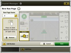 Layout manager module build
- Easily create page views that meet your needs and that are also equipped with default run pages.
- Users and access allow the owner or manager to lock out certain functions to prevent operators from accessing or changing settings with a defined four-digit code.
- Gather on-screen help by selecting the help icon on the shortcut bar on the bottom of every page.
Language and units
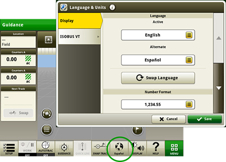 Switch between active and alternate language on the display
Easily switch between languages with the option to set the active and alternate language. Configure the shortcut bar to include the language toggle allows different individuals to easily switch the display between languages.
Machine monitor
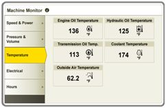 Machine monitor page
- The Machine Monitor application provides you instantaneous readings about the status or condition of your machine.
- This application shows parameters such as engine speed, coolant temperature, and ground speed.
Work monitor
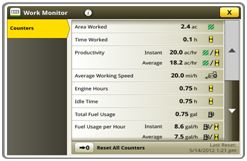 Work monitor page
- The Work Monitor application displays performance information about the task being performed by the machine.
- You are shown averages, totals, and productivity of the machine, such as area worked, average working speed, and fuel usage.
- Work setup places the settings needed to properly setup features such as AutoTrac, Documentation, and Section Control in a single location. Settings include:
- Client, farm, and field
- Crop type
- Machine and implement dimensions
- Variety/hybrid and planting/seeding rates
- Variable rate prescriptions
- Product and application rates
- Application rates through the implement screens
Video looping supported with Gen 4 4600 CommandCenter Display and 4640 Universal Display
- This feature enables users to scan or loop through all of the available video feeds for a specified duration. The default scan time is set to 7 seconds per image. The scan time is customizable per image allowing for consistent visibility to all video feeds.
Flags
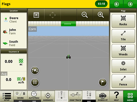 Create flags to mark items in the field
- Mark areas in the field that need special attention such as rocks, tile lines, or weed pressure.
- Flags previously recorded on the Gen 4 or GreenStar™ 3 2630 Display can be transferred between monitors.
- Flags previously recorded on the Gen 4 or GreenStar™ 3 2630 Display can be transferred between monitors.
Automatic base station switching
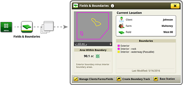 Setup base stations in Fields and Boundaries applications
- Customers using John Deere RTK Radio 450 or 900 can link a base station to a desired client,/ farm,/ or field. This allows automatic switching to the associated base station when changing fields. The ability to import base station assignments into Operations Center and send back to machines will be available at a later date.
Dual-display mode
 Dual display
- Generation 4 CommandCenter may be configured to run with the following John Deere displays connected at the cornerpost of a John Deere tractor:
- GreenStar 2 1800 Display
- GreenStar 2 2600 Display
- GreenStar 3 2630 Display
- 4640 Universal Display
- 4240 Universal Display
NOTE: Vehicle applications will always be located on the Gen 4 CommandCenter.
Video capability
- Machines equipped with a 4200 CommandCenter are equipped with one video input, and the 4600 CommandCenter has four video inputs.
- You have the ability to set a variety of triggers. With each trigger, the image will then appear on the display.
Field boundaries
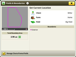 Boundary creation from coverage
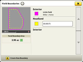 Headland creation
- Manually drive field boundaries with the Generation 4 CommandCenter or import existing boundary information from the GreenStar 3 2630 Display or John Deere Operations Center. Gen 4 documentation data can be used to create boundaries from coverage within the John Deere Operations Center.
- Easily create page views that meet your needs and that are also equipped with default run pages.
-
Hydraulic pump options to meet varying flow requirements
All 8R and 8RT Series Tractors come standard with an 85-cc displacement integrated hydraulic pump. This pump provides 227.1 L/min (60 gpm) of hydraulic flow.
A dual-pump option, featuring 85-cc and 35-cc displacement hydraulic pumps, is available for all 8R wheel models. The dual-pump system provides a hydraulic flow of 321 L/min (85 gpm), ideal for running at lower engine speeds.
SCV flow (approximate)
Engine rpm
Pump flow (85-cm3 pump) L/min (gpm)
High pump flow (85-cm3 pump + 35-cm3 optional pump) L/min (gpm)
800
86 (23)
122 (32)
1500
162 (43)
229 (61)
1700
184 (49)
260 (69)
1900
206 (54)
290 (77)
2100
227 (60)
321 (85)
Operating the tractor at reduced engine rpm contributes to a quieter cab, reduced fuel usage, and maintains the vacuum while turning and raising the planter on end rows. At 1500 erpm with a 321 L/min (85 gpm) system there will be an available flow of 229 L/min (61 gpm). This is an improvement over an available 162 L/min (43-gpm) flow when operating with a 227 L/min (60 gpm) system at 1500 erpm.
The maximum flow through one selective control valve (SCV) with a standard coupler is 132 L/min (35 gpm). A 19.1-mm (3/4-in.) high-flow coupler allows for a maximum flow rate out of one SCV of 153 L/min (40.5 gpm).
The hydraulic system is a closed-center, power-on-demand system using a load-sensing pressure-flow compensated axial piston pump with full-flow charge and flow prioritization for steering and brakes.
The pump outlet pressure available on demand can range from 3000 kPa (435 psi) for track models and 4000 kPa (580 psi) for wheel models at low standby to 20,400 kPa (2958 psi) at high standby.
Hydraulic pump options:
- 85-cc displacement, 227-L/min (60-gpm) hydraulic pump
- NOTE: Standard on all 8R models.
- 85-cc and 35-cc dual pump option, 321-L/min (85-gpm)
- NOTE: Compatible with 2014 Final Tier 4 (FT4) and newer 8R Wheel Tractors only.
- 85-cc displacement, 227-L/min (60-gpm) hydraulic pump
-
ActiveSeat™ seat utilizes electrohydraulic technology with air suspension
 ActiveSeat and controls
John Deere’s ActiveSeat utilizes electrohydraulic technology in combination with air suspension, providing the operator with enhanced ride quality over standard air-suspension seats.
Operator movements are monitored in order to reduce vertical movement. An ActiveSeat suspension can isolate the operator from up to 90 percent of vertical movements typically seen in tractor applications.
The system uses a hydraulic cylinder that is connected to a control valve assembly. Electrohydraulic valves located in the control valve assembly automatically react to inputs from two sensors, a position sensor and an accelerometer. Inputs from these two sensors control oil flow from the tractor to the hydraulic cylinder to reduce the vertical movement of the operator.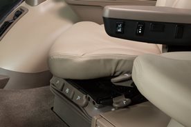 ActiveSeat left armrest
The John Deere ActiveSeat has many of the same features of the ComfortCommand™ seat with the addition of a ride firmness switch. The ride firmness switch is located on the left-hand armrest and replaces the suspension shock-dampening seat attenuation lever on the front right-hand side of the ComfortCommand seat controls.
The ride firmness switch has three positions: plus, minus, and mid position. The three positions provide three different levels of seat performance:- The plus position provides the greatest degree of ride firmness. This position allows more of the tractor's inputs to be felt by the operator (slightly rougher ride).
- The minus position provides the least degree of ride firmness, allowing minimal tractor inputs to reach the operator, resulting in maximum seat performance.
- The mid position allows a balance between the plus (+) and minus (-) settings.
The ActiveSeat is also available as a heated leather seat for increased comfort and easier cleaning. For tractor applications where operating speed is not limited by the implement, the ActiveSeat can allow for faster field speeds and increased overall comfort and productivity.
NOTE: The John Deere ActiveSeat is not available on track tractors.
Option code Description 2061 Premium CommandView III Cab with Active Seat -
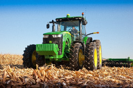
Tire options for 8R Series Tractors
John Deere 8R Series Tractors are utilized in numerous applications that place different demands on tires. As such, multiple tire offerings are available for 8R Series Tractors to accommodate a wide range of grower needs. Tire options provide variability in terms of ground clearance, tread width, and floatation to match different operating conditions.
John Deere sources 8R Series Tractor tires from the following major brands:- Mitas® tires
- Firestone® tires
- Goodyear® tires
- Michelin® tires
- Trelleborg® tires
Tire matching (rears and fronts)
 8R Series Tractor
Front and rear tires for 8R Series Tractors are sized and combined under different group sizes based on tire rolling circumference. All front tire options for 8R Series Tractors are classified as group 42, 43, or 44, while all rear tires are classified as group 47, 48, or 49. The approximate overall diameters for each group are shown in the following table.
Group Overall diameter 42 1498 mm (59 in.) 43 1600 mm (63 in.) 44 1676 mm (66 in.) 47 1955 mm (77 in.) 48 2057 mm (81 in.) 49 2172 mm (85.5 in.) For tractors with mechanical front-wheel drive (MFWD) or Independent-Link Suspension (ILS™) front axles, there typically needs to be five steps (or group size difference) between the front and rear tires to maintain proper tire overspeed between axles. This means the group 42 front tire needs to be matched with group 47 rear tire, and group 43 front tire needs to be matched with group 48 rear tire.
On 1500 MFWD axles, four-step combinations between front and rear tires are also acceptable (determined at the time of ordering the tractor). This means group 44 front tire can be matched with group 48 rear tire, or group 43 front tire can be matched with group 47 rear tire. Six step combinations are possible on tractors equipped with ILS, allowing group 43 front tires to be paired with group 49 rear tires in order to maintain narrower tread functionality with row crop width tire options.
Additionally, tires have a load index rating designed to report the load carrying capability of the tire.Group 49 rear tires
John Deere 8R Series Tractors are now approved for group 49 rear tires. Group 49 tires have a larger diameter and longer footprint, which results in greater traction in most field conditions compared to smaller group size tires of the same section width and basic design. Group 49 tires also provide a larger air volume than comparable smaller group sizes, which can help control power hop in some conditions.
NOTE:- Front tread spacing for group 49 tires (group 44 fronts) has to be 1930 mm (76 in.) or wider based on tire size. For 762-mm (30-in.) tread spacings, tractors equipped with ILS may be equipped with group 49 rear tires and group 43 front tires.
- 710/75R42 (group 49) tires are available in singles only (see Configurator for complete offering)
- 480/95R50 (group 49) tires are available in duals only (see Configurator for complete offering)
- Operators will experience a decrease in turning radius with group 49 tires due to the larger-diameter group 44 front tires.
Row width guidelines
Multiple tire options are available for 8R Series Tractors to accommodate multiple applications or row widths. Refer to the minimum recommended row widths for tire options based on the row-width requirements in the following table.
NOTE: Not all tires listed in the chart are available on all John Deere tractors. See your local John Deere dealer for assistance in choosing the proper tires for specific tractor models.Rear tires
Minimum recommended row width
508 mm
(20 in.)559 mm
(22 in.)762 mm
(30 in.)813 mm
(32 in.)1016+ mm
(40+ in.)Rear tire section width
RCI Group
Approximate outside diameter
320 mm
(12.6 in.)380 mm
(15.0 in.)480 mm*
(18.9 in.)520 mm*
(20.5 in.)620 mm
(24.4 in.)710 mm
(28.0 in.)
800 mm
(31.5 in.)
49
2175 mm
(85.5 in.)480/95R50
710/75R42
48
2057 mm
(81 in.)320/105R54
380/90R54
480/80R50
520/85R46
620/70R46
650/85R38
710/70R42
800/70R38
47
1956 mm
(77 in.)320/90R54
380/90R50
18.4R46
480/80R46
20.8R42
520/85R42
620/70R42
650/75R38
710/70R38
*480 and 520 width tires will accommodate minimum tread setting of 33 in. with 85L oil takeout.
Hitch clearance and tread spacing
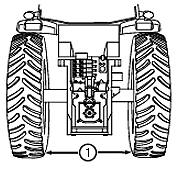 Tread spacing
To prevent draft link interference, the distance (1) between the inside edges of the tires should be:
- Category 3N hitch – 1092 mm (43 in.)
- Category 3 hitch – 1168 mm (46 in.)
- Category 4N hitch – 1168 mm (46 in.)
* Tires 480 mm (19 in.) and larger may not be able to reach all tread settings. Refer to the operator’s manual for detailed tread setting limitations.
Goodyear is a trademark of Goodyear Tire and Rubber Company.Firestone is a trademark of Bridgestone Americas Tire Operations, LLC.
Michelin is a trademark of MNA, Inc.
Mitas Tires North America is a registered subsidiary of MITAS a.s.
Trelleborg is a trademark of Trelleborg Wheel Systems, Inc.Front tires Minimum recommended row width 508 mm
(20 in.)559 mm
(22 in.)762 mm
(30 in.)813 mm
(32 in.)1016+ mm
(40+ in.)Front tire section width RCI Group Approximate outside diameter 290 mm
(11.4 in.)320 mm
(12.6 in.)380 mm
(15.0 in.)420 mm
(16.5 in.)480 mm
(18.9 in.)520 mm
(20.5 in.)620 mm
(24.4 in.)44 1676 mm
(66 in.)540/75R34 620/75R30 43 1600 mm
(63 in.)320/80R42 380/80R38 420/85R34 480/70R34 540/65R34 600/70R30 42 1499 mm
(59 in.)320/85R38 380/85R34 16.9R30
420/90R30480/70R30 540/65R30 600/65R28 Please reference the operator’s manual for tread spacing requirements.
-
Independent-Link Suspension (ILS™) utilizes industry-leading technology
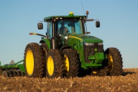
 8R Series Tractor equipped with ILS
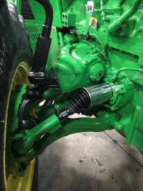 Close-up view of ILS design
The John Deere ILS utilizes industry-leading technology to supply unsurpassed gains to end-user productivity. This innovative design incorporates proven suspension design with mechanical front-wheel drive (MFWD) axle components that use state-of-the-art technology specifically for heavy equipment usage.
The ILS front axle is available on all 8R Series Tractor models.
42-km/h (26-mph) and 50-km/h (31-mph) front axles
Feature
ILS
Hydraulic differential lock
Yes
Limited slip
No
Suspension
Yes
Brakes
Yes (optional on 42 km/h [26 mph])
Tire ratio/steps allowed
5 or 6
Duals
Yes
Tread spacing singles*
1574 mm - 2184 mm
(62 in. - 86 in.)Tread spacing singles
1524 mm - 2235 mm
(60 in. - 88 in.)Singles with duals
1524 mm - 2235 mm
(60 in. - 88 in.)Duals
2946 mm - 3658 mm
(116 in. - 144 in.)Top speed
42 km/h (26 mph) or 50 km/h (31mph) depending on model
Front power take-off (PTO)
Optional
* Based on wheel equipment shipped to some geographic regions.
The ILS system gets more power to the ground because the front tires maintain ground contact pressure. This improves field and transport ride plus increases ballasting flexibility and drastically decreases the tendency to power hop.
ILS cutaway
The ILS axle maintains minimum oil levels in the front differentials to assist in providing overall tractor operating efficiency.
John Deere ILS has three systems:
- A mechanical system
- A hydraulic system
- An electrical system
Mechanical system
The mechanical system is further broken down into the mechanical drive system and mechanical suspension system.
The mechanical drive system includes:
- A three-position switch is included on a MFWD clutch.
- The MFWD clutch has six clutch discs and separator plates that can transfer as much as 40 percent of the tractor power through to the front ILS axle.
- The front differential transfers power from the engine to the individual right and left driveshaft through a ring and pinion.
- A hydraulically engaged front differential lock containing eight clutch discs and eight separator plates works in conjunction with the rear differential lock to assist the tractor in tough, wet conditions with increased power transfer to all wheels.
- A right and left constant-velocity telescoping driveline provides smooth power transfer to the outboard hubs.
- On 8245R, 8270R, 8295R, and 8320R Tractors, the ILS driveshaft speed is 6:1. On 8345R, 8370R, and 8400R Tractors, the ILS driveshaft ratio is 8:1. By using an 8:1 ratio on higher horsepower tractors, power can get to the wheels while minimizing the torque the U-joint experiences.
The mechanical suspension system consists of large cast, upper- and lower-control arms with cast steering knuckles for durability and reliability.
- There is a high steering capacity, even with dual wheels – 25 percent increase over model year 2013
- High torque in all steering positions provides maximum transfer of power to the wheels under all conditions
- Fully independent suspension maintains optimum ground contact at all times
Hydraulic system
The hydraulic system consists of suspension cylinders, a control valve manifold, a front differential lock, and hydraulic accumulators.
- There is a high steering capacity through large steering cylinders.
- Responsive link arms maintain contact with the ground surface, giving maximum tractive performance under any condition.
- Accumulators dampen energy from bumps to produce a smooth ride for maximum operator comfort.
Electrical system
The electrical system contains position sensors, solenoids for the control valves, and a master controller for complete automatic control of the ILS system.
How does it work?
The mechanical, hydraulic, and electrical systems work together to maintain a level and vertically-centered position of the front differential case in relation to the outboard hubs and planetaries, independent of tractor weight or dynamic loading. The system's ability to maintain a vertically centered position provides full suspension travel of 25.4 cm (10 in.). This translates to consistent soil contact for improved power to the ground as well as dampens the energy from bumps that cause a rough ride.
The tractor utilizes electronic and computer controls that monitor tractor functions and axle position. Based on those inputs, the electrical system automatically triggers hydraulic functions to raise, lower, or remain static.
The John Deere ILS uses a short/long A-arm design, which means the upper control arms are shorter than the lower control arms. During wheel movement, the upper control arm moves in a smaller arc than the lower control arm, and the difference in the two arcs creates a change in camber. The change in camber helps keep the inside and outside of the front tires perpendicular to the drive surface, a very important feature when optional front dual wheels are installed. This design provides anti-dive characteristics to naturally reduce the adverse effects of braking and acceleration.
The John Deere ILS front axle has been specifically designed to accommodate additional options, such as front 3-point hitches and front duals. To properly handle these options, large steering cylinders and knuckles provide up to twice the steering capacity of the standard MFWD beam axles so steering performance is maintained. A simple steering stop arrangement offers infinite adjustability for fine-tuning in any row spacing.
Braking system
With higher speeds and expected heavy towed implements and carts, front brakes are optional on 42-km/h (26-mph) ILS-equipped tractors and part of base equipment on 50-km/h (31-mph) ILS-equipped tractors. The braking system is applied proportionally between the front and rear axle brakes to effectively stop the tractor. There are no operator adjustments or requirements to operate the additional braking system.
Tire compatibility
For travel speeds of 50 km/h (31 mph), B-speed-rated tires that provide high-speed capabilities are required.
With the ability to have a six-step drop from rear to front tire, the 8R equipped with an ILS axle is able to have group 49 rear tires with group 43 fronts. This allows for the benefits of group 49 tires while maintain the turning radius allowed by group 43 front tires.NOTE: The use of group 44 tires for front duals does not allow for some row crop spacings.
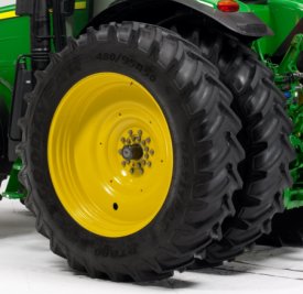
Front duals
 8R Series Tractor with front duals
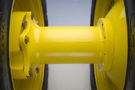 Narrow-diameter extension and hub attachment
Front dual tires provide:
- Ultimate flotation and compaction management
- Increased load-carrying capacity
- Easy installation or removal; no need to remove the inner tire
- Bolt-on components versus studded flanges for superior flexibility for dual/no dual applications.
- Narrow hub extensions to ensure superior crop clearance for row crop applications
- A serviceability port has been added to eliminate the need to remove the front dual and hub in order to change the hub oil at the required service interval
Hitch application
In hitch applications, it is important to maintain at least 50 percent of the ballasted front-axle weight (with implement raised) for steering control. Referring to the example below, the maximum ballasted weight of the front axle is 7756 kg (17,100 lb). If the tractor has a hitch-mounted implement, when the tractor is weighed with the hitch and implement fully raised, the front weight must be at least 3878 kg (8550 lb). The front axle capacity is directly proportional to the weight that can be carried on the hitch.
The MFWD axle has a front weight carrying capacity equal to the front tire carrying capacity. For example, in row-crop applications using the popular 480/70R34 (155 load index) front tires, the highest load rating is 3878 kg (8550 lb) per tire with a total of 7756 kg (17,100 lb) at maximum tire pressure. This means (depending on tire pressure and speed) there is as much as 3878 kg (8550 lb) available for support of rear implements in transport.
Maximum load carrying capacity of the axle is determined by the load carrying capacity of the tires and whether the tractor is equipped with singles or duals.
Additional ILS features:
There is no on/off switch for ILS operation since the John Deere advanced electronic management system knows when to disengage ILS automatically. The electronic controller will activate a restricted mode of operation, when any of the following conditions are met:
- Both brake pedals are pushed
- The 3-point hitch raise/lower switch is activated
- The tractor is placed in park
- Wheel speed is less than 0.5 km/h (0.3 mph)
- Tractor is correcting for an out-of-level condition
Based on the inputs received (speed, suspension displacement, braking and operator input to hitch and/or remote cylinders), the tractor determines when the system should be active or inactive, making operation simple and efficient.
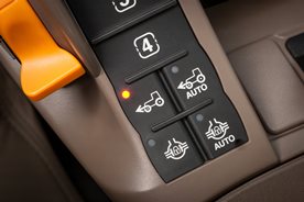
MFWD CommandARM™ controls for ILS
Shortcut keys on the CommandARM enable the operator to engage or disengage MFWD on the go, even under full load, without stopping or clutching. The switch can be placed in one of the following positions:
1. AUTO
2. On
3. Off (brake assist)Mode 1 - AUTO
 AUTO light
When this light-emitting diode (LED) light is lit, MFWD is on but automatically disengages when either of the following conditions are met:
- Either brake pedal is depressed and held to allow tighter turns
- Transporting at speeds above approximately 23.0 km/h (13.8 mph) to reduce tire wear; automatically engages when speed drops below 19.0 km/h (11.4 mph)
- When the front wheel turn angle meets an operator-defined point
As with the brake-assist position, when both brakes are depressed, the MFWD automatically engages (if not already on) to provide four-wheel braking.
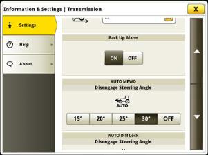 Automatic MFWD angle adjustment
Mode 2 - MFWD on
 MFWD light
When this LED light is lit, MFWD engages continuously.
Mode 3 MFWD off (brake assist)When no LED lights are lit, the MFWD is off. This is also referred to as the brake-assist position. Even though the MFWD is disengaged, when both brakes are pressed at speeds above 5 km/h (3 mph), the MFWD engages to assist braking the tractor.
Differential lock
 CommandARM™ controls with automatic differential lock engaged
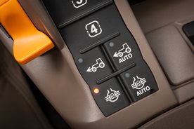 CommandARM controls with manual differential lock engaged
The differential lock is another feature of the ILS axle. When the rear differential lock is engaged or disengaged, the front differential lock is also engaged or disengaged. This also includes a driveline shield.
If one wheel begins to slip, the differential lock can be engaged on the go and the axles are hydraulically locked together for maximum traction. There are two ways to engage the differential lock feature.- Manual differential lock - differential lock can be engaged manually using a switch on the floor or by manually depressing a button on the CommandARM console. When brakes are depressed, the differential lock will disengage
- Automatic differential lock - when in auto mode, differential lock is engaged when the tractor is driving forward. Differential lock will disengage when front wheel turn angle meets disengage wheel angle setting defined by the operator via the CommandCenter or when either brake pedal is depressed. Differential lock will automatically engage when brakes are released or front wheels are turned straight.
Automatic differential lock angle adjustment
Additional equipment for use with ILS axle
- 3M front axle spacing kit:
Front axle static weight for the ILS axle shall not exceed 6759 kg (14,900 lb) using the 3M kit - H480 Front Loader
Refer to the material handling section for additional information.
-
Rear power take-off (PTO) options
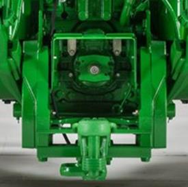 45-mm (1-3/4-in.), 1000-rpm PTO
All 8R and 8RT Series Tractors come standard with a fully independent 45-mm (1-3/4-in.), 1000-rpm PTO. This 20-spline shaft is designed for high-power, heavy PTO loads that require full horsepower above 150 PTO hp.
The 8R Series Wheel Tractors offer additional mechanical and electrical speed-change PTO options to provide the versatility and flexibility needed to satisfy implement demands. An in-cab shiftable, eco version of the 45-mm (1-3/4-in.), 1000-rpm PTO is available, allowing full PTO rotations at decreased engine speeds.
Additionally, a 45-mm (1-3/4-in.), 1000-rpm PTO capable of 35 mm (1-3/8 in.), 540-rpm (6 spline)/1000-rpm (21 spline) can be ordered. To field convert to the 35-mm (1-3/8-in.) 540/1000-rpm PTO, a field kit is required (the required shaft is dependent on the hitch option).
NOTE: 540-rpm PTO options are not compatible with the Category 4 drawbar.
The PTO activation switch is located on the CommandARM™ controls. In addition, PTO engagement modulation is adjustable with settings located in the CommandCenter™ display. The PTO shaft can be slightly rotated or indexed to aid in PTO drive hookups. All PTO options feature internal lubrication with heavy-duty oil-cooled clutch plates. A PTO safety start system and seat-activated PTO warning is standard on all 8R and 8RT Series Tractors.
The following tables show when shaft kits are required for each PTO shaft based on the selected hitch option (drawbar, 3-point hitch, 80-mm ball/piton).
1000/540 PTO
PTO type Nominal diameter, mm Number and type of splines PTO speed (rpm) Drawbar 3-point hitch 80-mm ball/piton 1 35 6 straight splines 540 RE272736 RE272736 R538037 2 35 21 involute splines 1000 RE272736 RE272736 R537791 3 45 20 involute splines 1000 OK from factory OK from factory OK from factory 1000/1000E PTO
PTO type Nominal diameter, mm Number and type of splines PTO speed, rpm Drawbar 3-point hitch 80-mm ball/piton 1 35 6 straight splines 540 No solution No solution No solution 2 35 21 involute splines 1000/1000E R537790 R537790 R313423 3 45 20 involute splines 1000/1000E OK from factory OK from factory OK from factory General applications:
- Use the 45-mm (1-3/4-in.), 1000-rpm PTO for full-power PTO applications, such as grain carts, rotavators, and silage choppers.
- Use the 35-mm (1-3/8-in.), 1000-rpm PTO shaft on implements requiring less than 150 PTO hp, such as manure spreaders and rotary cutters.
- Use the 35-mm (1-3/8-in.), 540-rpm PTO shaft on implements requiring less than 75 PTO hp (light loads only), such as auger applications.
NOTE: Proper engine speed for the 1000-rpm PTO shaft is 2000 engine rpm. For the 540-rpm PTO shaft, proper engine speed is 1817 rpm.
Rear PTO options:
- 45-mm (1-3/4-in.), 1000-rpm (20-spline) PTO
- NOTE: Compatible with 8R and 8RT Series Tractors.
- 45-mm (1-3/4-in.), 1000-rpm (20 spline), capable of 35-mm (1-3/8-in.), 540-rpm (6-spline)/1000-rpm (21-spline) PTO
- NOTE: Compatible with 8R Wheel Tractors.
To field convert to 35-mm (1-3/8-in.), 540/1000-rpm PTO, a kit will be required.
35-mm (1-3/8-in.), 540-rpm PTO portion of this option is not compatible with the Category 4 drawbar.
- NOTE: Compatible with 8R Wheel Tractors.
- 45-mm (1-3/4-in.), 1000-rpm and 1000E economy rpm PTO, in-cab shiftable
- NOTE: Compatible with 8R Wheel Tractors only. Not compatible with 16-speed PowerShift™ transmission (PST).
Includes 45-mm (1-3/4-in.), 1000-rpm (20-spline) shaft. See Parts for additional bolt-on shafts.
- NOTE: Compatible with 8R Wheel Tractors only. Not compatible with 16-speed PowerShift™ transmission (PST).
Capacities
| Crankcase oil volume | 1500 MFWD: 28 L 7.4 U.S. gal. ILS: 27.5 L 7.3 U.S. gal. |
| Fuel tank | Group 47/48: 615 L 162.5 U.S. gal. Group 49: 676 L 178.6 U.S. gal. |
| Cooling system | 32.6 L 8.6 U.S. gal. |
| Transmission-hydraulic system | MFWD: 140 L 37 U.S. gal. ILS: 165 L 43.6 U.S. gal. |
| Diesel exhaust fluid (DEF) tank | 23 L 6 U.S. gal. |
Dimensions
| Drawbar clearance | 376 mm 14.8 in. |
| Front axle center | MFWD: 686 mm 27 in. ILS: 590 mm 23.2 in. |
| Overall length | 6,636 mm 261.3 in. |
| Wheelbase | MFWD: 3,080 mm 121.3 in. ILS: 3,050 mm 120.1 in. |
Drawbar
| Maximum vertical load | 4,990 kg 11,000 lb |
| Drawbar category | Standard: Category 4 Optional: Category 4 with heavy duty support |
Electrical system
| Alternator size | Standard: 200 amp |
| Type of bulb in headlight (Halogen, Zenon, LED) | |
| Battery options | 12 V |
| Total cold cranking amps | 1,850 CCA |
| Type of bulb in beacon (Halogen, Zenon, LED) |
Engine performance
| Power boost | 10 percent |
| Engine peak torque | At 1600 rpm: 1,732 Nm 1,277 lb-ft |
| Rated power | 97/68EC: 272 kW 370 hp |
| PTO torque rise | 40 percent |
| Rated PTO power (hp SAE) | 233 kW 313 hp |
Engine specifications
| Rated speed | 2,100 rpm |
| Displacement | 9 L 549 cu in. |
| Aspiration | Dual series turbocharger with fixed geometry first stage-variable geometry second stage - air-to-air aftercooling and cooled exhaust gas recirculation |
| Engine type | Diesel, in-line, 6-cylinder, wet-sleeve cylinder liners with 4 valves-in-head |
| After treatment type | DOC/DPF/SCR |
| Engine family | JJDXL09.0308 |
| Emission level | Final Tier 4 |
Front axle
| Type | Standard: ILS Optional: 1500 Series MFWD |
| Front axle differential lock | 1500 Series MFWD: Full-locking electrohydraulic ILS: Full-locking electrohydraulic |
Front hitch
| Category | Category 3N |
| Front power take-off (PTO) | 44 mm (1.75 in) 20 spline, 1,000 rpm 35 mm (1.375 in) 21 spline, 1,000 rpm 35 mm (1.375 in) 6 spline, 1,000 rpm (available dependent on location) |
| Standard lift capacity | Category 3N ground engaging front hitch: 5,200 kg (11,464 lb) lift capacity |
| PTO speed | 1,000 PTO rpm at 2000 engine rpm |
Hydraulic system
| SCV control | Electronic |
| Pump rated output | Standard: 85-cc pump: 227.1 L/min 60 gpm Optional: 85-cc plus 35-cc dual pump: 321 L/min 85 gpm |
| Available flow at a single rear SCV | 0.5 in. couplers: 132 L/min 35 gpm 0.75 in coupler: 159 L/min 42 gpm |
| Available flow at front SCVs | 96 L/min 25 gpm |
| Type | Closed-center, pressure/flow compensated |
| Number of rear selective control valves (SCVs) | Standard: 0.5 in. ISO couplers: 9 Optional: 0.5 in. ISO Couplers: 5 and 6 available 0.75 in. ISO couplers: 6 |
Key Specs
| Rated PTO power (hp SAE) | 233 kW 313 hp |
| Rated engine power | 97/68EC: 272 kW 370 hp |
| Hydraulic pump rated output | Standard: 85-cc pump: 227.1 L/min 60 gpm Optional: 85-cc plus 35-cc dual pump: 321 L/min 85 gpm |
| Transmission type | Standard: e23 Powershit with Efficiency Manager™ 40K, 40 km/h 26 mph e23 Powershift with Efficiency Manager™ 50K, 50 km/h 31 mph John Deere AutoPowr™ IVT™ 40K, 26 mph (0.05-42 km/h) John Deere AutoPowr™ IVT™ 50K, 31 mph (0.05-50 km/h) |
| Base machine weight | ILS/e23: 14,270 kg 31,459 lb |
| Engine displacement | 9 L 549 cu in. |
| Engine description | Diesel, in-line, 6-cylinder, wet-sleeve cylinder liners with 4 valves-in-head |
| Rear hitch category (SAE designation) | Standard: Category 4N/3: 9,072 kg (20,000 lb) standard lift at 610 mm behind hitchpoint Optional: Category 4N/3: 6,803 kg (15,000 lb) at 610 mm behind hitchpoint |
Loaders
| Lift capacity at full height | 2,486 kg 5,469 lb measured at 800 mm ahead of pivot |
| Loader | H480 |
| Maximum lift height | 4,735 mm 186 in. |
Miscellaneous
| Country of manufacture | USA |
Operator station
| Cab glass area | 6.52 m2 70.18 sq ft |
| Inner cab volume | 3.597 m3 127 cu ft |
| Instructional seat | Standard |
| Rollover protective structure, OOS | |
| Radio | Standard: AM/FM stereo with weatherband, remote controls, auxiliary input jack, four speakers and external antenna |
| Cab suspension | Optional |
| Seat | Standard: ComfortCommand™ Optional: ActiveSeat™ |
| Display | Standard: 4100 Generation 4 CommandCenter™ with 7 in. display Optional: 4600 Generation 4 CommandCenter™ with 10 in. display |
Precision AG
| Remote diagnostics | Available with activated JDLink™ hardware and activations |
| Guidance | AutoTrac Ready |
| Telematic | Available with JDLink™ hardware, activations, and Ethernet Harnesses (availability dependent upon destination) |
Rear axle
| Final drive type | Inboard planetary three pinion |
| Type | Standard: Rack-and-pinion, double flat, or flange axles Optional: Long, dual taper hub: Diameter: 120 x 3010 mm 4.72 x 118.5 in. Short, double flat axle with single taper hub: Diameter: 120 x 2550 mm 4.72 x 100.4 in. |
| Rear differential lock | Full-locking electrohydraulic |
Rear hitch
| Sensing type | Electrohydraulic |
| Maximum lift capacity behind lift points | Standard: 12,124 kg (26,729 lb) at 610 mm behind hitchpoint |
| Hitch category (SAE designation) | Standard: Category 4N/3: 9,072 kg (20,000 lb) standard lift at 610 mm behind hitchpoint Optional: Category 4N/3: 6,803 kg (15,000 lb) at 610 mm behind hitchpoint |
Rear power take-off (PTO)
| Engine rpm (at rated PTO speeds) | IVT: 1,000 PTO rpm at 2,000 engine rpm 1,000 ECO PTO at 1594 engine rpm 540 PTO rpm at 1,814 engine rpm e23 PST: 1,000 PTO rpm at 1,995 engine rpm 1,000 ECO PTO at 1,590 engine rpm 540 PTO rpm at 1,810 engine rpm |
| Type | Independent Standard: 44 mm (1.75 in.) 20-spline, 1,000 rpm Optional: 44 mm (1.75 in.) 20-spline, 1,000 rpm/1,000E rpm |
Serviceability
| Interval for hydraulic/transmission oil change | 1,500 hours |
| Interval for engine coolant change | 6,000 hours |
| Interval for engine oil change | 500 hours |
Steering
| Type | Standard: Hydraulic power-steering with electric pump back-up Optional: ActiveCommand™ Steering (ACS) with electric pump back-up |
Tires
| Wheel tread range | 1500 Series MFWD: 1,524-3,657 mm 60-144 in. ILS: 1,524-3,657 mm |
| Turning radius without brakes | ILS with 380/85R34 group 42 tires at 60 in. spacing, |
Transmission
| Type | Standard: e23 Powershit with Efficiency Manager™ 40K, 40 km/h 26 mph e23 Powershift with Efficiency Manager™ 50K, 50 km/h 31 mph John Deere AutoPowr™ IVT™ 40K, 26 mph (0.05-42 km/h) John Deere AutoPowr™ IVT™ 50K, 31 mph (0.05-50 km/h) |
Weight
| Maximum ballast level | SAE PTO kW: 88.6 kg SAE PTO hp: 145 lb |
| Base machine weight | ILS/e23: 14,270 kg 31,459 lb |