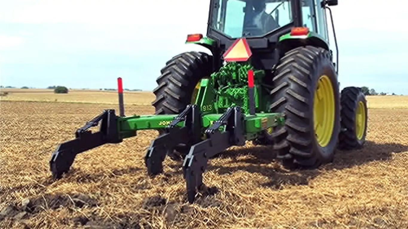
The soil probe helps operators to determine the proper operating depth of their ripper points, 38 mm (1.5 in.) below the bottom of the compaction layer.
The probe allows obtaining the maximum amount of soil fracturing from the entire family of John Deere ripper points. Marked in 51-mm (2-in.) increments from 254 mm to 559 mm (10 in. to 22 in.), the probe provides accurate feedback of compaction layer depth.
It is stored on the mainframe of the ripper for convenient access. The operator's manual explains the proper use of the soil probe.
Depth control
Option 1
Intergral units are controlled by tractor, rockshaft, and gauge wheels
Hitch
Options
Integral
Three-point hitch requirements
Category 2 or 3N with Quik Coupler Category 3N without Quik Coupler
Key Specs
Spacings
50.8 cm 20 in. 63.5 cm 25 in. 76.2 cm 30 in.
Operating depth
Maximum 58.4 cm 23 in.
Working width
Option 1: 2.5 m 8.33 ft Option 2: 3.2 m 10.42 ft Option 3: 3.8 m 12.5 ft
Transport width
Option 1: 2.1 m 7 ft Option 2: 2.1 m Option 3: 2.1 m
Operating depth
Maximum
58.4 cm 23 in.
Standard options
Spacings
50.8 cm 20 in. 63.5 cm 25 in. 76.2 cm 30 in.
Option 1
Trip force 5,443 kg 12,000 lb Standard type Straight or parabolic with wear shin Shear-bolt
Option 2
Trip force 2,540 kg 5,600 lb Standard type Straight with wear shin or parabolic Safety-trip
Option 3
Trip force 2,404 kg 5,300 lb Standard type Straight with wear shin or parabolic Cushion-trip
Option 4
Trip force 1,451.5 to 2,404 kg 3,200 to 5,300 lb Standard type Parabolic Spring-reset rock standard
Fill out this form to request a quote. A representative will get in touch with you as soon as possible.
Thank you for submitting.
Request Service
Fill out our request form to contact us about service.
Thank you for submitting.
Request Parts
Fill out our request form to contact us about parts.
Thank you for submitting.
Request Used Parts
Fill out our request form to contact us about used parts.
Thank you for submitting.
Request Rental
Fill out our request form to contact us about rentals.
Thank you for submitting.
Contact us about Precision Ag
Fill out our request form to contact us about precision ag technology.
Thank you for submitting.
Contact us
Fill out our contact form and a representative will be back in touch with you soon.
Thank you for submitting.
Learn More About Our Service Programs
Thank you for submitting.
Send us your feedback
We'd love to hear your feedback! Please fill out the form below to share.
Thank you for submitting.
Body Shop
Fill out this form to get in contact with our body shop. A representative will get in touch with you as soon as possible.
Thank you for submitting.
Papé Technician Training Program Interest Application
Thank you for submitting.
Technician Application
Thank you for submitting.
Events, Donations and Sponsorships
Thank you for submitting.
Join The Papé Team
Fill out our career form and a representative will be back in touch with you soon.
Thank you for submitting.
Contact us
Fill out our contact form and a representative will be back in touch with you soon.
Thank you for submitting.
Thank you for coming in, you are important to us! Please fill in your information below and one of our members will help you as soon as we can.
Thank you for submitting.
Thank you for your interest in electrification, you are important to us! Please fill in your information below and one of our members will reach out to you as soon as we can.
Thank you for submitting.
Giveaway Submission
Thank you for submitting.
Vaccination Status Survey
Thank you for submitting.
General Newsletter
Thank you for submitting.
Hawaii Newsletter
Thank you for submitting.
Request Dealer Transfer
Thank you for submitting.
Contact us
Fill out our contact form and a representative will be back in touch with you soon.
Thank you for submitting.
Thank you for your interest in upgrading to a premium John Deere compact utility tractor. Please fill in your information below and a Papé Machinery member will contact you shortly.