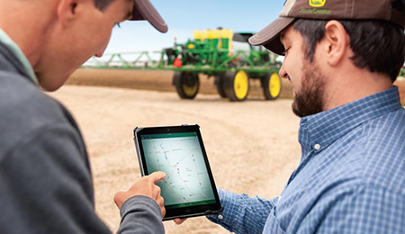
When you buy John Deere equipment, you expect reliability. You also know that problems can happen, and a product is only as good as the support behind it. That’s why John Deere equipment is prepared with technology that senses potential issues and can alert you and your dealer promptly—in the cab or anywhere you are.
John Deere Connected Support is a revolutionary change to support that leverages technology and the connectivity of JDLink™ telematics to prevent downtime and resolve problems faster. These tools decrease downtime by an average of 20 percent, enabling faster responses to unexpected problems and reducing technician trips to your machine. For some issues, unplanned downtime can even be prevented altogether through prediction of the issue.
With your permission, John Deere Connected Support:
Keeps you running by monitoring machine health and promptly alerting you and your dealer of issues
Saves time by remotely viewing in-cab displays, reducing trips to the machine
Reduces or even eliminates technician trips to a machine through remote diagnostic and remote software reprogramming capabilities
Connects experts with the information needed to respond to downtime faster and prevent it altogether
With more than a decade of experience leveraging connectivity to solve problems, no one else has the experience, tools, and knowledge to keep you running as John Deere and your John Deere dealer can. Connected Support is an in-base feature on all John Deere products with factory- or field-installed JDLink.
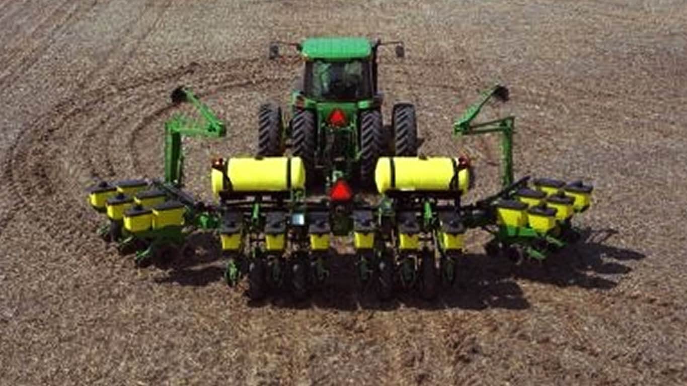
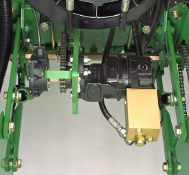
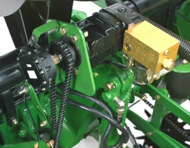
Seed variable-rate drive provides the ultimate planting productivity by utilizing one, two, or three hydraulic motors (varies by model) to turn the seeding drive shaft. Hydraulic control of the seeding drive allows for on-the-go seeding rate changes right from the display mounted inside the tractor cab. Combine this seeding flexibility with the map-based planting option, and seeding rates adjust automatically based on the prescribed map.
Variable-rate drive offers the following advantages over common, ground, or contact-tire drive systems:
Rate changes are almost instantaneous; no ramp up or ramp down of system as in some competitive systems
Permits the producer to match seed population based on different soil types or irrigation practices
John Deere design provides added operator safety by eliminating any possible drive creep found in some competitive variable-rate drive systems
1755 equipped with variable-rate drive
1765NT equipped with variable-rate drive
Single- or dual-motor systems for variable-rate drives are available for all John Deere planters except the 1785 Rigid Frame. Variable-rate drive is available as a factory-installed option for all applicable planter models.
Single- or dual-motor systems are available as field-installed attachments for most planter models; however, a three-motor variable-rate drive field-installed attachment is not available.
Seed variable-rate drive requires the SeedStar™ monitor and a radar input signal. Either tractor or planter radar may be used. Planter radar is ordered separately.
NOTE: Peanut seed meter disks require the variable-drive transmission.
IRHD has been specifically designed to meet the needs of producers that are looking to adjust to the toughest field conditions and provide maximum yield potential from field to field, season after season. IRHD works as a closed-loop downforce system that reacts quickly on an individual row basis to changing soil conditions supporting increased ground contact, which can lead to improved seed depth consistency. When setting planter downforce margin, the system will apply the needed downforce by row to maintain ground contact. From the factory, the margin will be set at 45.4 kg (100 lb), changes may be required based on varying field conditions.
The system allows operators to maintain gauge wheel ground contact leading to desired seed depth placement. IRHD can adjust five times per second and make adjustments of 45.4 kg (100 lb) in less than a second. The system has a total range of applied downforce from 22.7 kg (50 lb) to 204.1 kg (450 lb) and utilizes the power beyond circuit on the tractor. IRHD is 58 percent faster than the active pneumatic downforce solution. Fast reaction and increased ground contact can lead to improved emergence. With uniform emergence, some studies have shown a yield impact from 5 percent to 9 percent.
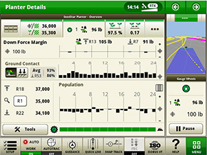
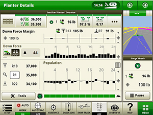
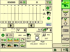
IRHD is controlled through the display with SeedStar™ 3 HP or SeedStar 4HP. As shown below, operators can view ground contact or applied downforce using the toggle button.
IRHD screen showing the ground contact graph through SeedStar 4HP
IRHD screen showing the applied downforce graph with SeedStar 4HP
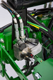
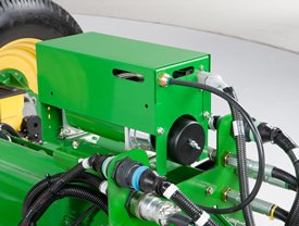
Hydraulically driven compressor
Pneumatic valve
The hydraulically driven air compressor can deliver up to eight times the air flow when compared to the electric compressor, allowing for more and faster downforce changes to be made. This more robust design features a 37.8-L (10-gal.) storage tank across all models with active downforce.
At approximately 15.1 L/min (4 gpm), hydraulic demands are low and ties into the machine’s lift and Central Commodity System (CCS™) hydraulic circuit so it does not require any additional selective control valves (SCVs). The SeedStar XP, SeedStar 3 HP, and SeedStar 4 HP monitoring systems work with the compressor. SeedStar 3 HP and SeedStar 4 HP monitoring systems work with the compressor and valve assembly to regulate air to downforce springs, enabling the active control, pneumatic closing wheels, and pneumatic row cleaners.
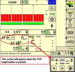
Row-unit downforce planter run page
SeedStar XP downforce planter run page
Active downforce control is integrated into SeedStar XP, SeedStar 3 HP, and SeedStar 4 HP monitoring systems.
Margin is the amount of weight riding on the depth gauge wheels that ensures desired firming of the seedbed as set by the operator.
Once a target margin has been defined, enter the value into the display and let active downforce do the rest. The system will actively adjust the air pressure in the air bags to maintain a constant margin across the planter. The changes in air pressure will change the amount of downforce placed on the row-unit, compensating and reacting for varying conditions through the field whether it is different tillage practices, soil types, or moisture.
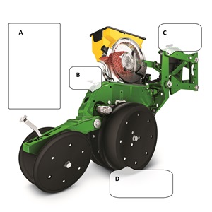
Downforce and margin example
A - Margin – amount of additional downforce applied to a row-unit above and beyond what is required for penetration to achieve planting depth. This additional weight will ride on the depth gauge wheels.
54.4 kg (120 lb) + 36.3 kg (80 lb) = 90.7 kg (200 lb) – 68 kg (150 lb) = 22.7 kg (50 lb) of margin
B - Weight of row-unit - 54.4 kg (120 lb)
C - Downforce – force that is applied to the row-unit by the air bag circuit - 36.3 kg (80 lb)
A hydraulically driven compressor works with the SeedStar XP, SeedStar 3 HP, and SeedStar 4 systems to automate downforce control. Just set the row-unit target margin value and the active pneumatic downforce system works automatically. The system will make sure the planter maintains this value, achieving precise soil penetration, and consistent planting depth, without sidewall soil compaction. From the factory, the system is set at 45.4 kg (100 lb) target downforce margin but may be modified for varying field conditions. This frees the operator from constantly making manual downforce adjustments as conditions change.
This system offers a split-rank control feature for 1795 and DB Split-Row Planters. On split-row planters, active downforce will control the front and rear rows independently. This compensates for differing downforce requirements between the ranks that can be caused by things like different tillage or insecticide attachments and will help maintain an accurate planting depth and consistent margin across all the rows.
Pneumatic downforce control in GreenStar 2 Display
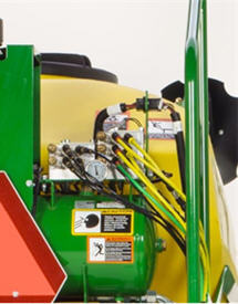
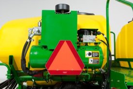
Air compressor mounted on 1775NT outer hitch
On set point, the air compressor will be mounted on the outer hitch or frame assembly. Since the electric air compressor assembly is mounted on the outer hitch (as noted in the picture above) or frame, adjustments for row-unit downforce and related system pressures will be made electronically with the GreenStar display.
When adjusting the amount of row-unit downforce using the GreenStar display, the operator will select the amount of downforce (kg [lb]) to be applied across the planter. Depending on the soil conditions at hand, the operator might need to adjust the relative amount of row-unit downforce being applied during the planting operation. The integrated pneumatic downforce controls within the GreenStar display will only allow for set-point operation and not automatic control as the planter is operating in different soil conditions. The pneumatic downforce system does not have the capability to automatically adjust downforce.
Pneumatic downforce provides convenient, simple adjustment of downforce for the whole planter from one location. The amount of downforce applied is infinitely adjustable from 6.8 to 181.4 kg (15 to 400 lb). Pneumatic downforce provides more consistent downforce throughout the range of row-unit travel than mechanical spring downforce systems.
Features include:
9.5-mm (3/8-in.) air delivery line instead of the 6.4-mm (1/4-in.) line used on model year 2010 and older planters.
Air compressor assembly increased duty cycle. With this compressor, it provides a 47 percent increase in maximum air flow delivery compared to the prior air compressor.
Pneumatic air bags with 9.5-mm (3/8-in.) air line inlets that have greater durability.
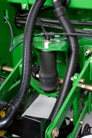
Pneumatic downforce spring
Each row-unit has a single rubber air bag located between the parallel arms. The air bags are hooked in parallel so that air can be added or released from all rows at once from one location.
The individual pneumatic downforce air bag assemblies, air compressor units, and 9.5-mm (3/8-in.) delivery lines are also available as an attachment for field conversion.
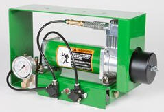
Pneumatic downforce compressor and gauge
An improved compressor is used to charge the pneumatic system. This compressor can be located on the planter frame or in the tractor cab if desired. A gauge at the compressor indicates the amount of downforce being applied.
Integrated pneumatic downforce system
The functional features of the integrated system are the same as the standard pneumatic system, explained above, with the addition of control through the GreenStar display.
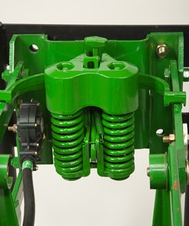
Heavy-duty adjustable downforce springs
Heavy-duty adjustable downforce spring
Planter row-unit downforce is an important factor to ensure consistent and proper depth control. The heavy-duty adjustable downforce feature provides up to 181.4 kg (400 lb) of downforce. There are four settings available to allow the operator to choose the amount of downforce required for the condition: 0 kg (0 lb), 56.7 kg (125 lb), 113.4 kg (250 lb), and 181.4 kg (400 lb).
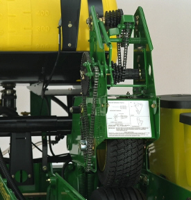
The tire contact drive for mechanical seed transmissions is a great fit for the mid-to-large planter operator concerned with quick transport capabilities, lower maintenance, and positive seed meter drives. The tire contact drive system is a simple, reliable, and efficient way to power seed transmission and meters.
The tire contact system drives the seed transmission mounted above the inner planter ground drive tire. A turf tire engages the ground drive tire when the planter is lowered, automatically turning the seed transmission and seed meters. Automatic drive disconnect occurs when the planter is raised and the turf tire separates from the ground-engaging tire. The system eliminates clutches, countershafts, and manual transport disconnects needed on direct ground drive systems. Drive chains and sprockets are moved up and out of the soil and residue zone for excellent reliability.
Tire contact drive systems are base equipment on the 1745, 1765, 1765NT, 1775 12-Row, and 1785 Planters. Contact between the ground-engaging tire and seed transmission tire is positive. On all models mentioned, a spring set applies downforce of the turf tire assembly onto the ground-engaging tire. System slippage is also minimized because the planter drive tires track in the tractor tire tracks. Frame designs differ (such as tire width) and the following different downforce requirements exist:
1765 8-Row drives have 207.3 kg (457 lb) of downforce.
1765 and 1775 12-Row drives have 254 kg (560 lb) of downforce.
The 1745 model uses one front-mounted seed transmission, and if the planter is equipped with fertilizer, another front-mounted transmission is utilized. The 1765 model uses one rear-mounted seed transmission. However, if the planter also has the fertilizer option, there is another rear-mounted transmission for the fertilizer drive. The 1785 Rigid Planters utilize one front-mounted seed transmission, and if the planter is equipped with the liquid fertilizer option, another front-mounted transmission is utilized. The 1775 12-Row Planter utilizes two rear-mounted seed transmissions. Another rear-mounted transmission is used if the planter has the fertilizer option.
MaxEmerge 5 bundles the best of MaxEmerge XP and Pro-Series™ XP row-units to give you a unique planter solution. With more options and configurations, you’ll get difference-making versatility that easily adapts to your ag management plan.
It starts with optimal seed population that drives yield potential. An improved double eliminated helps achieve your desired population with a ride range of crop sizes. Improved side-hill performance of up to ¼ degree ensures you receive the full value of each seed when planting on terraces or rolling terrain. The vacuum air source from the Central Commodity System (CCS™) tank in the meter provides a debris-free environment for increased meter efficiency.
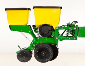
MaxEmerge 5 with 56-L (1.6-bu) hopper plus insecticide
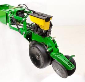
MaxEmerge 5 with mini-hopper on CCS™ machines only
The MaxEmerge family of row-units have never seen a more versatile and efficient design until the MaxEmerge 5. The 5-family row-units improve productivity, increase uptime and lower the cost of ownership like never before.
The MaxEmerge 5 row-unit was designed for improved performance and serviceability.
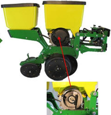
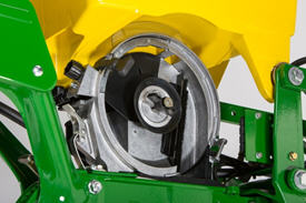
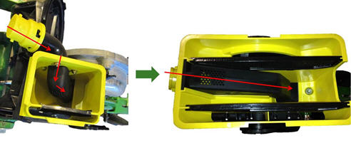
Easily access the meter
Serviceability and changing crops have always been a focus of downtime and potential seed loss. The MaxEmerge 5 meter (shown on the right) is accessible without having to remove the box. The design allows large hoppers to be cleaned out the same as mini-hoppers, simply by opening the meter dome and catching the seed as it falls out.
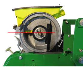
MaxEmerge 5 vacuum seed meter
The vacuum meter system gently pulls and holds individual seeds to the holes of the seed disk for population control and spacing accuracy, equaling better crop stands and profit. Vacuum seed meters can plant a wide variety of crops and seed types by simply changing seed disks and adjusting vacuum level. Vacuum seed meters are available for planters with MaxEmerge 5 row-units.
Additional features of the vacuum seed meter include:
One moving component (the seed metering disk) for minimum maintenance requirements
Meter located at each row-unit for accurate seed delivery
Good hopper seed flow characteristics for longer operating time per hopper fill
Low airflow in meter so seed treatments are not removed
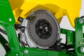
MaxEmerge 5 seed pool
The MaxEmerge 5 meter shape has also been redesigned for better seed flow. The mini-hopper design allows the planter to successfully operate on side hills up to 14 degrees.
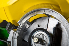
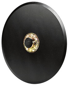
Vacuum meter hub and latching handle
MaxEmerge 5 vacuum meter with disk
Both the MaxEmerge 5 vacuum meters are equipped with a heavy-duty hub spring and disk latching handle. The spring ensures the seed disk stays properly positioned when operating flat-style seed disks and higher vacuum levels. Proper seed disk positioning means repeatable seed singulation, time after time. The disk-latching handle is designed for easy operation and effortless seed disk changeover. The hub is also machined to tight tolerances to further ensure alignment of metering components.
Operating characteristics of vacuum seed meter
Operating speed with seed tube technology
The vacuum seed meter can operate at faster planting speeds than mechanical meters. However, planting accuracy will be influenced by seedbed conditions and the operating characteristics of the seed meter. Rough seedbeds and fast planting speeds (above 8.9 km/h [5.5 mph]) typically deteriorate seed placement accuracies when using seed tube technology.
The chart illustrates the effect operating speed has on population when using the vacuum meter. The operating band (color area) illustrates how the vacuum meter performs in relation to the desired population (indicated by horizontal line). The width of the band is due to various sizes and shapes of seeds and planting rate variations.
When operating on slopes above 15 degrees, increased or decreased population may result. To minimize this effect, reduce speed and consider using a flat style seed disk with increased vacuum level.
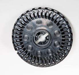
Vacuum meter seed disks
The ProMax 40 Flat Disk is a flat-disk planting solution field-proven to work since 1991.
ProMax 40 Flat Disc
The design of the ProMax 40 Flat Disk position allows seed to be released from the optimum position above the seed tube. The flush-face seed tube allows the seed to drop uninterrupted through the tube.
The ProMax 40 Flat Disk utilizes flat holes and a higher vacuum level to ensure every hole is populated with a seed. A double eliminator gently removes multiple seeds at each hole for precise population control. A knockout wheel makes certain that each hole is clear of any debris after the seed is released from the disk.
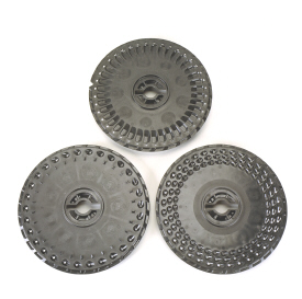
Flat-style and cell seed disks shown
The unique cell disk design allows planting a variety of seed sizes without any additional parts or individual meter adjustments. Another advantage of cell-type seed disks is the lower vacuum requirement compared to flat-style seed disks. Lower vacuum levels mean less hydraulic demand from the tractor. Most planting conditions call for a flat disk, if you are limited in hydraulic capacity, cell disks are recommended.
Double eliminator
Flat seed disc and double eliminator
For difficult to singulate seeds, a flat seed disk and double eliminator is a viable alternative to traditional cell-type seed disks. By design, a flat seed disk requires higher levels of vacuum than a cell-type disk because there is no pocket or cell to hold the seed. The higher vacuum level will pull more than one seed to the holes in the seed disk. The double eliminator is set to cover a portion of the hole in the seed disk and is the mechanism to knock multiple seeds away as the disk rotates.
Double eliminators are required with flat-type seed disks only and should not be used with cell-type seed disks. The knockout wheel is also recommended in conjunction with the double eliminator and flat seed disk to ensure seed is ejected from the disk.
Flat and celled type seed metering disks are available to allow planting a wide variety of seed types.
Corn (field, popcorn, or sweet corn)
Soybeans
Cotton
Sorghum
Sugar beets
Sunflowers
Edible beans/peas
Peanuts
Melons, squash, cucumbers
Mini-hopper row-units, which are used only with the CCS, are compatible only with crops that the CCS is approved to plant.
Corn
Popcorn
Sweet corn
Soybeans
Sunflowers
Sorghum
Cotton
NOTE: Due to small seed size and low planting populations, sugar beets can be planted with mini-hopper style meters by adding hopper extensions and not using the CCS tank. These hopper extensions can also be used for planting test plots.
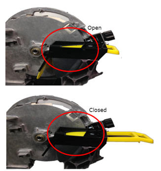
Hopper shutoff
Also, to help with meter access of 56-L and 106-L (1.6-bu and 3-bu) hoppers the hopper shutoff feature was added. With the shutoff engaged, the meter cover can be opened without first having to remove all the seeds from the hopper. Lever down, the seed flow is on, lever horizontal and the seed flow is off.
MaxEmerge 5 mini-hopper
There are significant changes to the MaxEmerge 5 mini-hopper. One update is the straight feed from the CCS hose to the mini-hopper to ensure a continuous free flow of seeds. This design change reduces the potential for plugging issues with larger seed size and the use of seed treatments. By drawing air from the CCS tank, the vacuum source is cleaner, preventing meter debris buildup.
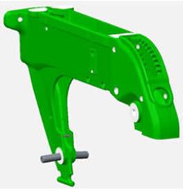
Ductile iron-cast shank
Ductile iron casting is a unique high-tech process that produces a single-piece row-unit shank this enables alignment from the seed trench to the closing wheel.
The row-unit head is also designed using the ductile iron-casting process. The row-unit head provides the mating joints between the row-unit parallel arms and the row-unit shank. It is also the upper attaching point for the seed meter and seed hopper.
Ductile iron casting of the row-unit shank and head assembly provides a row-unit that is 25 percent stronger than other competitive welded row-units.
Tru-Vee opener blade
One of the trademark capabilities of John Deere planters has always been the ability of the Tru-Vee openers to provide an ideal seed furrow.
The thickness of the Tru-Vee opener blade is 3.5 mm (0.14 in.) this blade thickness will provide extended wear life.
The MaxEmerge 5 row-unit also provides better Tru-Vee opener bearings for longer life. The double-row ball bearing provides up to three times the wear life as the single-row bearing.
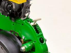
Depth adjustment T-handle
John Deere planters provide consistent seed depth control in all field conditions. Depth control is a function of the Tru-Vee openers, the downforce system, and the gauge wheel assembly.
The gauge wheel itself is made of durable nylon composition with a concave profile. This profile gently firms the sides of the seed furrow, ensuring a well-defined trench. The shape reduces rocks and residue being picked up and thrown onto the drive chains and row-units, and helps to prevent rooster tailing of soil.
The bolt-through design utilizes an open bearing in the gauge wheel that allows an attaching bolt to pass through the wheel to the threaded hole in the gauge wheel arm. This simple bolt-through design provides for a positive attachment of the gauge wheel to the gauge wheel arm and allows quick removal of the gauge wheel for service.
Adjustability of the row-unit is critical to good performance. More available downforce options than any row unit in the industry
Adjustable heavy-duty downforce, four settings, 0 kg (0 lb), 57 kg (125 lb), 113 kg (250 lb), and 181 kg (400 lb) of downforce
Pneumatic downforce, infinitely variable from 0 to 181 kg (0 to 400 lb) of downforce
Active pneumatic downforce adjusts automatically for changing ground conditions from 0 to 181 kg (0 to 400 lb) of downforce
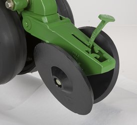
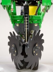
Rubber tire closing system
Cast wheel closing system
Rubber tire closing systems are used for most conventional, minimum-till, and no-till planting conditions. The spacing between the wheels is adjustable so the closing system can meet the needs of those who want to plant small seeds at shallow depths.
The wheels can also be staggered fore and aft to enhance residue flow. Four levels of spring force are available and are easily set with the integrated T-handle adjustment. A lower force spring can be obtained from parts, if a lower amount of force is required.
Additional closing wheel options include:
Cast closing wheels for tough-to-close conditions
Disk closing, for shallow planting depths
Closing wheel frame less wheels for growers desiring to use aftermarket closing wheels
Designed with conventional, mulch-till, and no-till planting conditions in mind
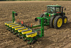
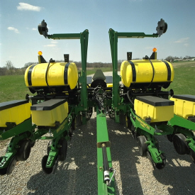
1765NT Drawn Wing-Fold Planter
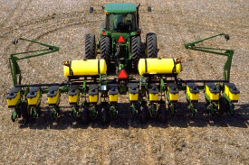
1765 12Row30 Drawn Wing-Fold Planter
Both the 1765 and 1765NT (narrow transport) feature a rugged 177.8-mm x 177.8-mm (7-in. x 7-in.) frame, wheel module lift system, and tire contact drive system. The 12Row30 flexible-frame model feature a two-section, center flexing frame design that flex 20 degrees up and 20 degrees down. The 1765 and 1765NT are recommended for conventional, mulch-till, and most no-till planting conditions.
The 1765 Planter family is available in the following frame configurations including both rigid and flex options:
8Row30 Narrow Transport (NT) rigid frame
12Row30 rigid frame
12Row30 flex frame
Frame functionality
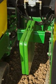
1765 Flex center frame weight bracket
For 1765 and 1765NT Wing-Fold Planters that are operating less fertilizer or would require more frame weight for tough soil conditions, additional weight can be added to the center frame. A mounting bracket and six weights add approximately 272.2 kg (600 lb) to the planter. This weight prevents the frame from flexing up in the center when planting.
Use AA41141 ballast bracket and six tractor front end weights. Attach the bracket with seven 19M7597 (M20x50) bolts and 14M7277 nuts.
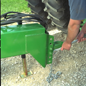
Tractor attaching options
1765 and 1765NT Planters offer one hitch length
Adjustable hitch settings to match tractor height
The 1765 and 1765NT Wing-Fold Planters have one hitch length available: 373.4 cm (147 in.) for planters used with a dual-wheel-equipped tractor. The long 373.8-cm (147-in.) hitch options are available for all frame widths and can be equipped with either a clevis (code 2820) or ring (code 2810) style hitch link. Order the style of hitch link desired.
Hitches are adjustable, providing three hitch settings to match tractor drawbar height, resulting in level planter operation.
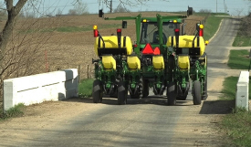
Transportability
1765NT Planter transports at 3.7 m (12 ft)
Narrow Transport (NT) planters provide a compact transport width of only 3.7 m (12 ft).
Wing folding of all 1765 Planters is hydraulically-controlled. The independent marker option and hydraulic-fold option are plumbed together using a diverter valve (code 868A) when both options are ordered (reduces selective control valve [SCV] requirements by one).
Model
Transport width with markers
Transport height*
8Row30 NT
3.7 m (12 ft)
3.3 m (10.75 ft)
12Row30
4.8 m (15 ft, 8 in.)
3.05 m (10 ft)
*Height measured with 18.4R-46 rear tires on tractor
Fertilizer capabilities
Both the 1765 and 1765NT Planters can be equipped with a liquid fertilizer system. Eight-row configurations carry two fertilizer tanks totaling 1135.6 L (300 gal.) of capacity. The 1760 12Row30 model can handle 1703.4 L (450 gal.) of fertilizer in two tanks.
The use of the single-disk, unit-mounted injection fertilizer opener or the frame-mounted, single-disk fertilizer opener makes the 1765 and 1765NT no-till capable. The 1765 equipped with the unit-mounted, double-disk fertilizer opener is not well suited for no-till applications and opener penetration may be limited by soil conditions. Frame-mounted, single-disk fertilizer opener is only compatible with 1765NT Planters.
Crop yields have increased through the years along with the amount of residue left in the field after harvest. At the same time, tillage practices have changed, including different tillage operations which maintain large amounts of surface residue, and even no-till practices. Row cleaners are an essential tool in managing this increased amount of residue.
John Deere seeding group offers a variety of row cleaner options to meet the needs of a producer's operation. Compatibility varies by model, row spacing, and other planter equipment.
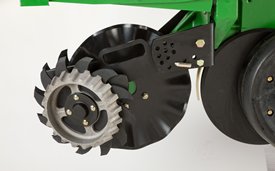
Screw-adjust, unit-mounted row cleaner
Screw-adjust, unit-mounted row cleaner
The screw-adjust, unit-mounted row cleaner is mounted directly to the face plate of the row-unit, placing the ground engaging components just in front of the row-unit opener blades and depth gauge wheels. This close proximity allows the gauge wheels to control the depth of the row cleaner as well as the row-unit. This compact design also allows greater compatibility with fertilizer openers and other planter attachments.
SharkTooth® wheels are standard equipment on the unit-mounted row cleaner. The swept-tooth design of the wheel provides a clear path for the row-unit openers while resisting residue buildup on the wheel. The screw adjustment knob is accessible through the top of the parallel arms, providing convenient access for adjustments. The row cleaner can be adjusted in 1.6-mm (1/16-in.) increments, providing plenty of flexibility to meet the needs of changing conditions.
Floating row cleaner with unit-mounted coulter
Floating row cleaner with unit-mounted coulter
The floating row cleaner allows a row cleaner to be used in conjunction with a unit-mounted coulter. This combination is often desired in heavy residue loads and reduced tillage planting conditions. The row cleaner provides a clear path for the row-unit, while the unit-mounted coulter helps penetrate tough soil conditions.
Accommodating the unit-mounted coulter means the residue wheels are farther forward from the row-unit face plate than in the case of the screw-adjust row cleaner. To maintain performance, this row cleaner has the capability to float above a defined minimum depth.
Standard depth-gauging bands on the wheels allow the row cleaner wheels to float independently of the row-unit openers, allowing both to perform in varying terrain. The unit may also be set in a fixed position by simply pinning through the bracket if desired. This row cleaner also features SharkTooth wheels as standard equipment.
The floating row cleaner and unit-mounted coulters are available on many planters as factory-installed equipment.
NOTE: Screw-adjust row cleaners are not compatible with MaxEmerge™ 5e row-units with long parallel arms.
NOTE: DB models have the option for either unit-mounted coulter, screw-adjust row cleaners, or pneumatic row cleaners (only compatible with MaxEmerge 5e or equipped ExactEmerge™ models). The DB60T is only available with a less row cleaner option.
SharkTooth is a trademark of Yetter Manufacturing, Inc.
Closing System
Rubber tire closing system
Cast iron closing system
Dimensions
Transport height
8-Row: 3284 mm 10.75 ft 12-Row: 3429 mm 11.25 ft
Transport weight
Average frame weight: 4410 kg 9720 lb
Field operation length
Short hitch: 8-Row: 4647 mm 15.25 ft 12-Row: 4647 mm Long hitch: 8-Row: 5406 mm 17.75 ft 12-Row: 5406 mm
Transport width (with markers)
8-Row: 3630 mm 11.92 ft 12-Row: 4775 mm 15.67 ft
Field operation width
8-Row: 6540 mm 21.42 ft 12-Row: 8811 mm 28.92 ft
Drive System
Base
Sprocket and chain from drive wheels or Hydraulic variable rate drive
Fill out this form to request a quote. A representative will get in touch with you as soon as possible.
Thank you for submitting.
Request Service
Fill out our request form to contact us about service.
Thank you for submitting.
Request Parts
Fill out our request form to contact us about parts.
Thank you for submitting.
Request Used Parts
Fill out our request form to contact us about used parts.
Thank you for submitting.
Request Rental
Fill out our request form to contact us about rentals.
Thank you for submitting.
Contact us about Precision Ag
Fill out our request form to contact us about precision ag technology.
Thank you for submitting.
Contact us
Fill out our contact form and a representative will be back in touch with you soon.
Thank you for submitting.
Learn More About Our Service Programs
Thank you for submitting.
Send us your feedback
We'd love to hear your feedback! Please fill out the form below to share.
Thank you for submitting.
Body Shop
Fill out this form to get in contact with our body shop. A representative will get in touch with you as soon as possible.
Thank you for submitting.
Papé Technician Training Program Interest Application
Thank you for submitting.
Technician Application
Thank you for submitting.
Events, Donations and Sponsorships
Thank you for submitting.
Join The Papé Team
Fill out our career form and a representative will be back in touch with you soon.
Thank you for submitting.
Contact us
Fill out our contact form and a representative will be back in touch with you soon.
Thank you for submitting.
Thank you for coming in, you are important to us! Please fill in your information below and one of our members will help you as soon as we can.
Thank you for submitting.
Thank you for your interest in electrification, you are important to us! Please fill in your information below and one of our members will reach out to you as soon as we can.
Thank you for submitting.
Giveaway Submission
Thank you for submitting.
Vaccination Status Survey
Thank you for submitting.
General Newsletter
Thank you for submitting.
Hawaii Newsletter
Thank you for submitting.
Request Dealer Transfer
Thank you for submitting.
Contact us
Fill out our contact form and a representative will be back in touch with you soon.
Thank you for submitting.
Thank you for your interest in upgrading to a premium John Deere compact utility tractor. Please fill in your information below and a Papé Machinery member will contact you shortly.