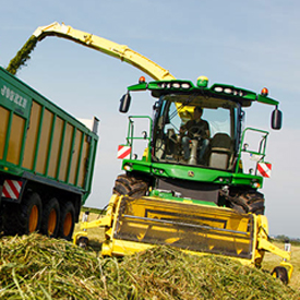
Power-efficient crop handling and machine propulsion in the field are critical to maximum field performance on given engine power.
On the 8000 Series Self-Propelled Forage Harvester (SPFH), this is addressed through a unique machine layout leading to a fully harmonized crop path, avoiding any abrupt change of flow direction in the channel.
The 8000 Series machines feature automatic header detection, which automatically triggers all relevant calibrations and pre-settings memorized on the machine controllers.
Header lateral ground adaptation as well as a driveline synchronized with the machine crop feeder, or an optional dual header drive where the pickup tine reel would adapt the machine forward speed, and the feed auger speed would be in line with the feedroll speed, are leading to unobstructed crop entry into the harvester. Capacity and harvesting quality is maximized.
Advanced header control and active header guidance on corn heads allows precise header positioning through feelers, while the head is not in contact with the ground, resulting in an absolutely even stubble field.
Header attaching comfort is unmatched. Operations are reduced to manually applying the locking lever, and quick-coupling electric and hydraulic services.
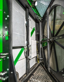
The entire cooling package for the 8000 Series Self-Propelled Forage Harvester (SPFH) cooling system can be accessed from the service compartment in the middle of the machine. Everything can be reached easily in one spot on the machine, making daily servicing convenient. The constantly rotating radiator screen allows a wide opening angle for easier service. No tools are required for servicing the air filters. The filters can be reached when standing on the left side of machine in the service room.
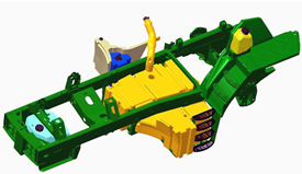
Fuel tank
Fuel tank
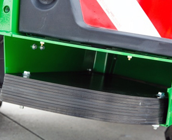
The standard 1100-L (290.6-gal.) fuel tank and 43-L (10.6-gal.) urea tank are located in the low center and on the low center left-hand side of the machine. This guarantees a low center of gravity. Both tanks’ filler necks are accessible from the cab stairs. Refueling is done from one single position.
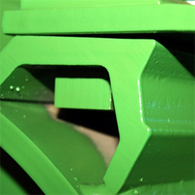
Cutterhead access
35 degree V-opening
Feedroll door opening
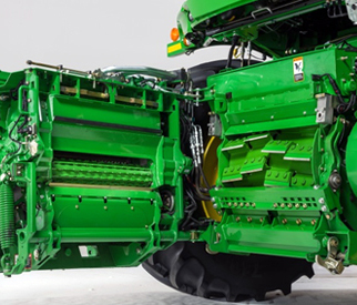
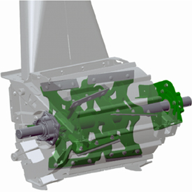
The 8000 Series cutterhead unit concept provides two methods to access the shear bar and cutterhead for inspection or maintenance.
Leaving the header mounted on the machine and releasing the top locking mechanism together with the top side pivot pin, while the lower clamps remain locked, allows access to the shear bar and the knives through a 35-degree V-opening.
Detaching the header and releasing the upper and the lower locking mechanisms, provides convenient access through a feedroll door opening action, similar to the 6000 and 7000 Series Harvesters.
ProDrive is the industry-leading ground-drive propulsion.
Due to weather conditions, the harvesting window becomes shorter and in some areas around the globe, the machine has to work under very wet and soft soil conditions. This leads customers to get a forage harvester which can manage harvesting in these varying conditions.
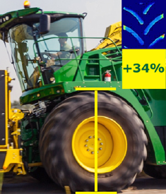
The 8000 Series with the ground-drive-propulsion ProDrive, in conjunction with largest tires in the industry and optimized weight distribution, leads to maximum performance and uptime in soft soil conditions.
The largest tires, with a diameter of 1067 mm (42 in.) and a width of 900 mm (35.4 in.), deliver in comparison to a 7000 Series tires, a 34 percent larger footprint helps the 8000 Series with increased traction as well as less ground compaction.
The 8000 Series performs without compromises due to the industry-leading ground clearance, especially in soft soil conditions.
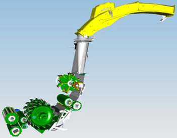
A key concept for the 8000 Series Self-Propelled Forage Harvester (SPFH) line was to position all crop-flow components to avoid any restrictions, as well as to design the crop path for minimum kinetic friction on the particles.
The 8000 Series crop-flow channel begins at the harvesting unit pickup tines or crop-row pointer. On the actual harvester, it starts with the feedroll arrangement. John Deere has implemented a concept layout well proven on the 7000 Series.
Key characteristics are a set of front feedrolls where, when the header interface is in a vertical position; the upper-front feedroll (UFFR) reaches out about 60 mm (2.4 in) over the crop in front of the lower one, grabbing the mat from the harvesting header and pulling it into the feedroll gap. This is a key function when corn headers without feed augers are mounted; assuring the machine’s crop feeder is the sole length-of-cut (LOC) metering unit of the harvester.
On its way to the cutterhead, the radial-arc-feed roll arrangement applies pressure to the crop for superior cut quality. The crop mat is perfectly compressed until the last second before transitioning into the knives.
From the moment the knife pockets start unloading, the cutterhead band takes the crop particle stream, collecting it for launching into the crop chute.
The crop path follows a constant curve between the cutterhead floor and the accelerator entrance. The crop accelerator, the spout transition, and the spout build the machine’s crop discharge device. All components that have an acceleration impact on the crop perfectly integrate tangentially into this curve for a fully unobstructed crop flow.
With 1800 rpm, the accelerator provides sufficient thrust to the crop stream for loading with the largest of heads without consuming excessive power. Rather than being carried by the accelerator rotor, the crop follows the curve of the accelerator band before moving through the transition directly into the spout base, from where on it follows the spout contour.
The crop hits the transition front liner just below the spout entrance at a shallow angle, minimizing component wear and inertia losses. This constant flow curve was designed to the spout as gently as possible so that the crop flow components had the least friction effect on the crop particles.
Sufficient space on the vehicle for a cab that allows for more operator leg room, though keeping the overall machine compact, was a key demand.
Ultimately, the 8000 Series SPFHs provide superior crop-flow efficiency, resulting in industry-leading machine capacity in respective horsepower classes as well as low-specific-fuel consumption (amount of diesel per ton of crop harvested). Combined with Dura Line™ technology, the 8000 Series SPFH triggers the lowest possible machine maintenance with minimal cost of operation.
8000 Series crop discharge
Crop accelerator
Crop accelerator
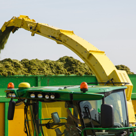
On its way to the trailer, the crop must be elevated more than 4 m (13 ft) high between the accelerator exit and the spout end. It must overcome a certain friction along the transition and spout liners until it is ejected off the spout end cap. When opening corn fields, producers can expect crop being airborne over a distance of 15 m to 20 m (50 ft to 65 ft) into the following trailer.
It is the task of the crop accelerator to provide sufficient thrust with appropriate efficiency to the crop particles to be loaded in all circumstances. An exactly specified air inlet in the accelerator housing assures a perfect spout crop jet when the kernel processor is installed.
Crop transition
The crop transition is completely lined with high-grade wear elements, which can easily be inspected and replaced from the machines service compartment through an access hatch. A unique manufacturing process allows even, customized hardening of the wear liners, perfectly addressing the individual wear situation in the cone. The transition is bearing the massive head gear-driven spout turning mechanism.
8000 Series SPFH features a spring-loaded cam-torque limiter inside the spout-turning drive mechanism. The spout hitting an obstacle is perfectly secured. However, the spout would never rotate uncontrolled and hit the cab. The spout turning sensor precisely monitors the spout position even when the spout clutch would have been triggered and mechanical end stops additionally secure the system.
Spout with multiple length components
Spout
The spout on the 8000 Series features modular architecture. On the basic module, the wear liners are a structural part of the component. This module features a box design closed by the wear liner. A worn-through liner discovered too late would not lead to damage of the spout structure, but replacement would rebuild the spout like new.
The liner of the base module is segmented addressing the wear situation on individual sections. In the standard configuration, all four liners on the base module are made of Hardox® steel; however, for severe conditions, section one and two can be specified in Dura Line™ version.
When specified with HarvestLab™, section two would carry the near-infrared (NIR) sensor. In this case, the wear liner always comes in Dura Line™ version, and it would feature quick-attach clamps for easy maintenance of the HarvestLab sensor.
The HarvestLab installation is easy and is completed by directly bolting it to the wear-liner segment. The NIR sensor is once aligned with the carrier sheet, and whenever serviced, the entire assembly is then unlatched from the spout and then re-clamped.
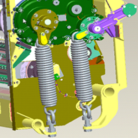
Header mounting and ground contour following
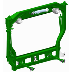
Header mount
8000 Series front-end interface is a laterally tilting frame. Multiple factors led to John Deere’s common harvesting units interface plate and redesigned header mounting, including:
The need for more front feedroll travel as well as a greater roll diameter addressing the increased harvesting capacity of the new line.
The intention to integrate the lateral tilt device into the harvester vehicle, because the larger feedrolls of the machine would not allow for enough tilt with the combine interface.
The ground adaptation can be passive, with a set of springs bringing back the frame into neutral level position or active (optional) with a hydraulic cylinder, positioning the header in reference to the signals from AHC sensors on the respective header.
This change eliminates multiple lateral-tilt devices on headers. An additional advantage is the header's self-centering feature of the attaching cones on the frame required to implement the automatic header drive-shaft coupler. Central header locking is a standard feature and comes with the hydraulic multi-coupler.
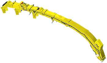
High-arc spout showing available extensions
There is a set of intermediate spout extensions of various lengths addressing the loading distance relative to SPFH header width. For weight reasons, the spout extensions are built from aluminum alloy with a thin steel liner inside. The spout end-cap module bolts to those intermediate sections.
The standard configuration shipped from the factory would be dedicated to grass harvesting with a windrow pickup or corn harvesting with a 6-m (20-ft) corn header. A second spout segment to extend the spout for 7.5-m (25-ft) header width can be by-packed with the harvester. For 12-row, 9-m (30-ft) corn harvest, a foldable spout segment is available.
IVLOC™
Infinitely variable length of cut IVLOC
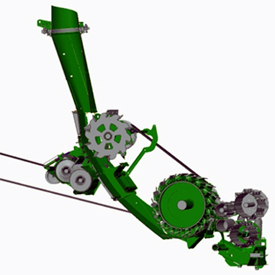
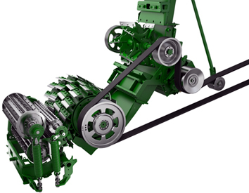
The entire feeder assembly is driven from the main feedroll transmission on the right-hand side of the roller frame. Power is sourced from the hydrostatic motor. The static set of lower-front feedrollers is directly driven from the gearcase. The moving set of upper-front feedrollers have their proper transmission on the left-hand side supplied with power via a transversal U-joint shaft. The main concept driver is to allow wider crop channels inside a narrower machine fit with the biggest tires in the industry.
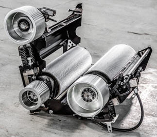
Crop intake
Crop intake rolls
Mechanical spring
Both series of self-propelled forage harvesters (SPFH) use four feed rolls to ingest crop with the top rolls pulled down by four springs. Their tensioning can set manually. All four rolls are driven with an infinitely variable transmission and speed synchronized to ensure smooth and reliable feeding of the cutterhead.
Feedrolls
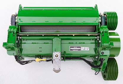
The front set of feedrolls in charge of taking the crop off the front-end harvesting unit have been redesigned to be more adaptive to the tremendous variability of harvesting conditions.
The upper-front feedroll (UFFR) is now solely a ridge-type design and standard fit with replaceable and reversible wear teeth. The ridges feature a triangle-teeth design and are part of the roll segments. Behind the ridges there are tapered composite teeth bars clamped on the segmented roll. The wear slats feature the same triangle-teeth design on one side and are smooth on the other side, which makes them ideal to adapt the roll to the full range of crop conditions from dry and smooth hay to wet and sticky alfalfa.
The lower-front feedroll (LFFR) features a similar design; however, replaceable teeth bars with identical serration are optional wear elements. Inside the lower front feedroll is a rectangular tube carrying the metal detector coils, helping the operator to enjoy full machine and crop protection.
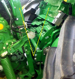
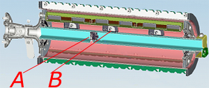
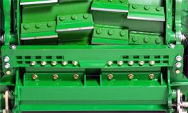
Machine foreign-object protection
A points to the stone detector and B points to the metal detector sensors
The well-known and proven electromagnetic metal-detection system with its multi-sectional sensor coil is standard on all John Deere SPFHs. When tripping, metal object location in the crop mat is indicated in the cab. Also, the metal detector would trigger the selective control valve (SCV) 1 on the SPFH to automatically raise the crop compressor device on the grass pickup. Re-engaging the feedrolls would then lower the device into place again.
As an option, the metal detector can be completed with an additional stone detection feature where a sensor is placed inside a rectangular tube within the lower front feedroll. This sensor is correlated with a second sensor located on the right-hand side of upper front feedroll arm. One sensor detects stones striking the lower roll, as the other detects rapid feedroll movement of the upper roll. Both sensors work together, and as a result the verification of a solid foreign object is significantly improved, minimizing stone detector false tripping.
When the sensor is tripped, the feedrolls stop both with the metal detector or stone detector and automatically raises the crop compressor device on the hay pickup. Re-engaging the feedrolls would then lower the device into place again.
Stone detection offers a competitive advantage in the marketplace as it detects not only large stones or rocks, but small ones as well using knock sensors. This system provides operators with peace of mind while chopping in rocky conditions to prevent damage to the SPFH. Detecting stones and preventing them from entering the crop path of the machine not only reduces damage to the machine but also lowers the cost of operation and increases uptime to the customer which leads to increased productivity and performance.
Header drive and control
The 8000 Series SPFHs supply crops to the chopping components.
Improvement is driven by automatic header detection, variable and efficient hydrostatic header and feeder drive concept, revised header ground contour following, sophisticated machine protection technology, and feedroll redesign.
Automatic header detection
8000 Series machines are equipped with the multicoupler interface for all hydraulic and electric services to the SPFH harvesting headers. Through the electric wiring coding in the multicoupler, distinct header identification is assured, allowing it to automatically refer to customized header settings stored in the respective controllers onboard the SPFH. This allows the operator to instantly call back all settings that resulted from the last harvesting experience. All calibrations required for proper header operation are automatically recalled in full when attaching the header.
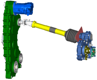
Hydrostatic header drive
Hydrostatic motor
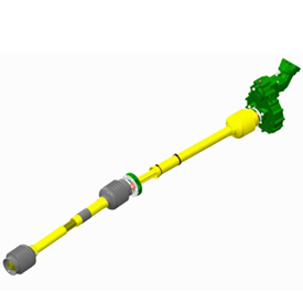
On the 8000 Series, the harvesting headers are driven by a hydrostatic service. The hydrostatic pump on the machine’s main power take-off (PTO) transmission supplies power to the motor behind the vehicle front axle. A U-joint shaft assembly transmits the torque to the header entry transmission.
An optional dual-header drive provides a power split to the feeding components such as on a grass windrow pickup. In this case, the hydrostatic service would drive the pickup auger and a second hydraulic service would separately power the pickup tine reel.
Variable oil-flow control allows easy synchronization of drive speeds with the velocity of respective components on the harvester. The entire header can be driving with a constant speed setting, or the header main drive can turn at a desired speed ratio synchronized with the harvester’s feedroll speed.
The dual drive allows individual synchronization of the header feed auger with the feedrolls and the header tine reel with the vehicle’s forward speed when harvesting.
Capacity, harvesting quality, machine efficiency, and total cost of ownership have always been important differentiators for self-propelled forage harvesters (SPFH). Machine size, weight, or soil compaction associated with weight, and tire size is critical to producers' acceptance of certain machines on their fields. A key demand on the 8000 Series was to find a machine layout for optimum weight distribution and maximum capacity potential.
The driveline concept has been optimized for maximum flexibility in setting the individual component speeds and also synchronizing certain functions for maximum harvesting quality. Specific component design has been implemented to improve efficiency.
Components have been laid out for matching the power demand, not only of today’s producers, but also meeting potential requirements of future users.
Most advanced wear-resistance technology is applied on all crop-flow elements to assure full-season harvesting uptime. Longer component wear life significantly lowers the cost of ownership.
The unique Dura-Drum™ cutterhead design, together with the portfolio of cutterhead configurations, allows 8000 Series machine owners to perfectly specify their harvesters for meeting all operating demands. Three different cutterhead configurations with 10, 12, or 14 lines of knives, a full or half set of knives, and in conjunction with 1100 or 1200 cutterhead rpm provide an overall range of length of cut (LOC) from 3 mm (0.12 in.) up to 52 mm (2 in.). The 8000 Series Self-Propelled Forage Harvesters (SPFH) meet any customer requirements.
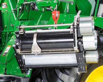
Kernel processor technology
John Deere Premium KP™
John Deere XStream KP™
Industry-leading crop processing technology, such as from a conventional roller kernel processor, or from the latest XStream KP disk processing technology characterizes the 8000 Series approach to highest harvesting quality, essential for maximum performance.
8000 Series SPFH can be equipped with crop reprocessing technology, resulting in corn silage samples complying with highest-quality standards and kernel processor scores. Crop processing principles are implemented on the harvesters reflecting the various crop conditions as well as the harvesting capacity of the machines relative to their engine power.
In the 8100 and 8200 models, the John Deere Premium KP is installed in base.
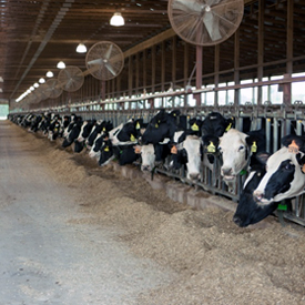
On machines in the higher performance classes (8300 – 8600), the choice between the John Deere Premium KP and the John Deere XStream KP allows for tailoring a machine exactly to the needs and requests of dairy or biogas producers. The metabolic speed of crops in meat production or ultra-high performing dairy cows or a biogas digester is essential, where the fermentation speed is the key to the economic success of the plant.
To address different crops and crop abrasiveness, different rolls can be selected. Furthermore, the speed differential can be altered, addressing the processing requirement relative to predominant crop maturity or moisture.
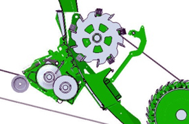
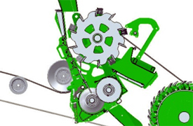
With the swing-in/swing-out concept, the kernel processor can be easily set to its working or storing position. The swing-in/swing-out is conveniently done in the machine service compartment. The processor swaps with a crop transition chute with just a few turns. In short-term alternating application, the processor can stay in its parking location. When it is not needed for a longer time, an optional articulating lifting beam with an electric hoist allows convenient removal from the machine.
Kernel processor swing out
Kernel processor swing in
Kernel processor
Chopping technology
Rotor flywheel design
8000 Series SPFHs feature the unique John Deere Dura-Drum™ design. The cutterhead's distinct flywheel design or the retracting knife segments protecting the rotor against destruction by foreign objects remain unchanged. Cutterhead speed is set at 1100 rpm at rated engine speed.
Although the main crop flow components have been relocated in the machine, key features like a short spiral cutterhead band and the reverse knife sharpening method assure the advantages of exceptionally low power demand for cutting and crop transition remain on the 8000 Series.
On the cutterhead, the regular spiral cutterhead band can be replaced with a recutter floor featuring a set of mower bar knife sickles sticking out into the crop flow. The chopped crop mat is screened while passing the floor, so that leaves or longer crop particles are re-cut for perfect chopping results under adverse conditions.
Such a recutter floor can also be provided as a by-pack with the machine from the factory.
Cutterhead
Cutterhead
Cutterhead
All 8000 Series machines are narrow body and come with a standard harvest channel. The feedroll channel measures 660 mm (26 in.). A drum equipped with knives is 12 mm (0.5 in.) wider on either side, assuring a uniform crop flow across the full width of the cutterhead. This prevents uneven wear on knives, which would cause poor shear bar setting and result in poor chop quality.
When rebuilding seasonally with new knives on 8000 Series, the cutterhead is a fixed dimension, and the cutterhead housing is then adapted to the drum size with shims under the housing wear liners. By doing so, it is assured that the cutterhead is perfectly seated in the housing, safely preventing crop particles from bypassing the drum alongside the side walls.
The cutterhead diameter has been set to 670 mm (26.4 in.), complete with knives to allow for 12-knife rows on the rotor’s circumference as well as addressing the crop unloading angle into the redesigned crop transition. The higher number of knives significantly improves the machine's harvesting capacity when chop length needs to be extremely short.
8000 SPFHs use heavy-duty knife equipment. Knives are 9 mm (0.4 in.) thick and feature extra-long 20-mm (0.8-in.) hard facing. The knives are longer, allowing a sufficient knife overhang; this allows using up the entire hard facing on the knives without the necessity of relocating them, and still retain efficient crop throwing to the kernel processor or crop accelerator.
The knife carrier profile has been improved so that there is no negative impact on the crop transition from an extended knife pocket unloading cycle. This configuration also avoids premature crop stream funneling in front of the critical kernel processor processing gap.
Cutterhead design and configuration options, including a Dura Line™ option where the individual knife carriers are hard faced, specifies a machine for its desired application.
The operator can choose between two adjusting cycles:
After a grinding activity the procedure is interrupted to allow knife inspection, only the grinding icon on the display is lit.
Knife grinding and shear bar setting are performed successively without interruption, both grinding and shear bar icon on the display are lit.
Shear bar options are also offered.
SPFH
8100-8600
Feed opening - front and rear
655 mm x 220 mm (25.8 in. x 8.7 in.)
Effective feed opening
655 mm x 237 mm (25.8 in. x 9.3 in.)
Cutterhead housing width
686 mm (27 in.)
Cutterhead width with knives
680 mm (26.8 in.)
Cutterhead diameter with knives
670 mm (26.4 in.)
Cutterhead 64 carrier without knives
352 kg (776 lb)
Cutterhead 56 carrier without knives
334 kg (736 lb)
Cutterhead 48 carrier without knives
318 kg (702 lb)
Cutterhead 40 carrier without knives
301 kg (664 lb)
Grass/corn knife weight
0.9 kg (2 lb)
Shear-bar setting range
19 mm (0.7 in.)
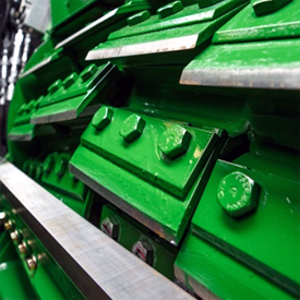
Shear bar
Shear bar configuration
The traditional knife/shear bar configuration does not change at all. There are significant design and handling changes implemented on these machines, conceived to deliver a much higher performance.
The shear bar is fixed with three bolts on a massive cast-steel anvil. This anvil is mounted on bearing spring plates out of high tensile yet flexible steel. This shear-bar anvil design allows asymmetric shear bar traveling to address potential one-sided cutterhead wearing through systematic off-center machine loading.
A second design change driver was on the natural shear-bar wearing cycle; the generic bending forces between knives and shear bar would be significantly elevated on machines with higher-capacity potential. The middle fixing prevents the shear-bar gap from increasing in the machine's center assuring perfect crop-cut quality throughout the entire life cycle of the shear bar.
On the 8000 Series, remote electronic knife sharpening and shear-bar setting come standard. The machine automatically applies the right shear-bar setting method appropriate to the cutterhead maintenance situation.
An extended setting procedure is automatically applied when a new shear bar has been installed and set the first time, or whenever the operator has had the shear bar intentionally travel away from the cutterhead.
This is a more complex adjustment logic assuring a shear bar is set absolutely parallel to the knife line, independent from the initial shear bar position.
After a normal periodic knife grinding, a shear bar quick-adjustment logic would move both sides of the bar simultaneously to final position.
Blower/Crop accelerator
Number of blades
10
Speed (option)
1800 rpm
Rotor diameter/housing width
Rotor diameter: 560 mm 22.86 in. Housing width: 540 mm 21.26 in.
Cab
Tilt and extend steering column
Standard
Air conditioning and heater
Standard - ClimaTrak
Cool box
Optional
Hectare counter
Standard
Electric adjust and heated
Optional on rear view mirrors
CAN bus electronics
Standard
Rearview mirrors
Standard
Trainee seat
Standard Leather seat optional
Side window wiper
Rear and side window wiper optional Parallel-type windscreen wiper
Heavy duty housing with KP roll quick exchange system
Bearing temperature monitoring system
Optional
Lubrication
Pressurized oil
Speed differential / Roll speed (lower)
50 percent
Available KP rolls
Duraline sawtooth Duraline XCut Whole crop XCut
Roll diameter
250 mm 9.84 in.
Kernel processor
Quick-change
Quick kernel processor - swing in/swing out
Quick KP removal
Optional: Crane with remote-controlled electric hoist
Type
Premium KP (8100-8600) XStream KP (8300-8600)
Key Specs
Fuel system
Unit injector plus four valves
DEF tank capacity ( for FT4 or EU Stage V emission level)
43 L 11.4 U.S. gal.
Maximum power
430 kW 585 PS / 577 hp
Engine
Type PowerTech™ PSS 13.5L Exhaust emission regulation compliancy - Final Tier 4 / Stage V Displacement 13.5 L 823.8 cu in. Model Europe: 6135HZ021 North America: 6135HZ022 Cylinders Inline 6
Fuel tank capacity
1.1 L 290.6 U.S. gal.
Knife sharpening system
Reverse rotation
Yes
Automatic from cab
Yes, remote from cab
Reverse drive
Standard
Sharpening modes
Grinding and finishing
Length of cut
Range
Range at 1100 rpm: 40 knives: 7-26 mm (0.275-1.0 in.) LOC / 1 mm (0.04 in.) steps 48 knives: 6-22 mm (0.24-0.87 in.) LOC / 1 mm (0.04 in.) steps 56 knives: 5-19 mm (0.20-0.75 in.) LOC / 1 mm (0.04 in.) steps Range at 1200 rpm: 56 knives: 4-17 mm (0.16-0.67 in.) LOC / 1 mm (0.04 in.) steps 64 knives: 3-15 mm (0.12-0.59 in.) LOC / 1 mm (0.04 in.) steps
Machine management solutions
Assisted steering systems
AutoTrac or Manual RowSense optional
Length-of-cut control based on crop parameter
Infinitely variable length-of-cut (IVLOC™) standard AutoLOC™ optional with HarvestLab 3000
Yield monitoring
Harvest Monitor™ optional
Crop analysis
HarvestLab™ 3000 optional
Documentation
Harvest Doc™ optional
Maintenance
Rotary radiator screen cleaner
Standard
Automatic lubrication system
AutoLube optional
Engine oil and filter change duration
JD+50™ II oil: 500 hours Other oil: 250 hours
Propelling drive
Standard
Hydrostatic, 3-speed - manual shift with helical gears
Spout
Rotation, degrees
210 degree (angle)
Double-cap deflection
Standard
Hydraulic height position
Hydraulic raise and lower standard Automatic spout positioning optional
Very poor machine, unreliable, underpowered. Have had two 8500i harvesters in the last 3 years very unhappy customer having owned John Deere foragers for 10 years
Fill out this form to request a quote. A representative will get in touch with you as soon as possible.
Thank you for submitting.
Request Service
Fill out our request form to contact us about service.
Thank you for submitting.
Request Parts
Fill out our request form to contact us about parts.
Thank you for submitting.
Request Used Parts
Fill out our request form to contact us about used parts.
Thank you for submitting.
Request Rental
Fill out our request form to contact us about rentals.
Thank you for submitting.
Contact us about Precision Ag
Fill out our request form to contact us about precision ag technology.
Thank you for submitting.
Contact us
Fill out our contact form and a representative will be back in touch with you soon.
Thank you for submitting.
Learn More About Our Service Programs
Thank you for submitting.
Send us your feedback
We'd love to hear your feedback! Please fill out the form below to share.
Thank you for submitting.
Body Shop
Fill out this form to get in contact with our body shop. A representative will get in touch with you as soon as possible.
Thank you for submitting.
Papé Technician Training Program Interest Application
Thank you for submitting.
Technician Application
Thank you for submitting.
Events, Donations and Sponsorships
Thank you for submitting.
Join The Papé Team
Fill out our career form and a representative will be back in touch with you soon.
Thank you for submitting.
Contact us
Fill out our contact form and a representative will be back in touch with you soon.
Thank you for submitting.
Thank you for coming in, you are important to us! Please fill in your information below and one of our members will help you as soon as we can.
Thank you for submitting.
Thank you for your interest in electrification, you are important to us! Please fill in your information below and one of our members will reach out to you as soon as we can.
Thank you for submitting.
Giveaway Submission
Thank you for submitting.
Vaccination Status Survey
Thank you for submitting.
General Newsletter
Thank you for submitting.
Hawaii Newsletter
Thank you for submitting.
Request Dealer Transfer
Thank you for submitting.
Contact us
Fill out our contact form and a representative will be back in touch with you soon.
Thank you for submitting.
Thank you for your interest in upgrading to a premium John Deere compact utility tractor. Please fill in your information below and a Papé Machinery member will contact you shortly.